Mastering the techniques in this chapter will enable you to perform operations that you might have thought impossible. Layouts and setups are featured that will add a professional dimension to your projects.
Drill Press Mode – Setup and Features
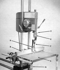
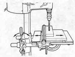
Use the accessories shown in Figure 7-1 for drilling operations. To set up your Mark V in the drill press mode, follow the instructions in the Owners Manual that came with your machine.
As you work in the drill press mode, you’ll find that the Mark V is an extremely capable drill press with several special features:
- The distance from the chuck to the table can be adjusted to 26″ and from the chuck to the floor to 58″.
- The drill chuck holds bits with shanks 3/64″ to 1/2″ in diameter.
- The quill extends up to 4-1/2″, and the depth control (quill feed stop) can be set to automatically stop the quill at any point from “0” to 4-1/4″.
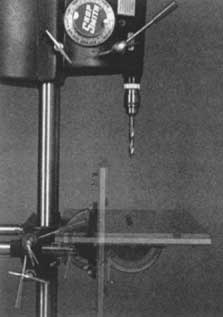
- The table tilts from “0” to 90-degrees Figure 7-2.
- The rip fence and miter gauge can be used to help hold and position workpieces.
- With a wide range of speeds, the Mark V can drill a wide range of materials-wood, plastic, and metal.
Drill Bits
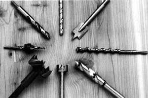
There are three types of drill bits commonly available to woodworkers: twist bits, used to drill both wood and metal; spade bits, used when rough splintered holes are acceptable; and power auger bits, which drill slower and leave a smoother hole than either twist or spade bits Figure 7-3. There are also specialty bits: brad-point, Forstner, multispur, screw drills, and plastic-drilling.
Most woodworkers aren’t half as concerned with the type of bit they use as they are with the quality of the hole it leaves. As mentioned, in the course of a single project you might drill dozens of different holes for many difterent functions. For almost every hole you can imag-ine, there is a bit designed to make it a little better and a little easier to drill.
General Purpose Holes–Brad-point bits (also called machine spur bits) are a vast improvement over twist bits. A small point at the bottom of the bit bites into the wood first, holding the bit on center so it will not wander. Two side spurs slice through the wood grains to make a clean entrance, leaving a clean hole. Brad-point bits are your best choice for general drilling in wood. However, they should not be used to drill other materials.
Twist bits, usually associated with metal drilling, can be used to make holes in hard or soft woods. The hole will be rougher than you might want, and there can be considerable feathering or splintering when the bit breaks through, even when the work is supported on scrap stock.
Super-Smooth Holes–Decorative holes and holes for pivoting dowels need to have extremely smooth, splinter-free sides. Forstner bits were designed for just this purpose. They will bore small, shallow holes with flat bottoms and polished sides. Multispur bits will also bore flat-bottomed, smooth-sided holes, but they are designed to drill much deeper and much larger holes than Forstner bits.
Screw Holes–Screw bits will drill a pilot hole, shaft hole, and countersink for wood screws all in one operation. They can be ad-justed for different lengths of screws.
Holes in Plastic–To avoid cracks and splinters, use plastic drilling bits to drill holes in plastic. Plastic-drilling bits will drill clean holes in many types of plastic.
If you drill mostly in wood, we suggest you start with brad-point bits. While they can be purchased individually, it’s a good idea to begin with an assortment that includes the most useful sizes-1/4″, 3/8″, 1/2″, 5/8″, and 3/4″. A complete set of brad-point bits start at 1/8″ and increases to 1″ in increments of 1/16″.
The flutes in a bit are channels that guide waste material out of the hole. If the channels are clogged, waste will back up and both bit and wood will burn. That is why you should not drill deeply enough to bury the flutes. On most jobs it is good practice to retract the bit frequently so waste can be ejected. Adjust feed pressure to the job you are doing and the speed you are using. A heavy feed will clog the cutter; one that is too light is just as bad because the bit will do more burnishing than cutting.
Provide good storage for your bits so they’ll keep clean and can’t be knocked around.
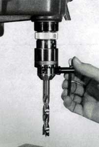
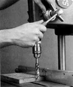
Drill bits are secured in the chuck with a key that causes the chuck’s jaws to close firmly about the shank of the bit Figure 7-4. Be sure to allow enough shank for the chuck to grip.Warning: Remove the key from the chuck immediately after securing the bit.
Drill Press Saftey
Warning: Before using the drill press, read and understand these important safety instructions:
Danger Zone–The danger zone on the Mark V in the drilling mode extends 3″ all around the bit and chuck and 5″ beneath the bit. The reason for the extended danger zone beneath the bit is that the quill moves the bit in that direction. Always keep your fingers and hands out of the danger zone.
When you work at the drill press, pay attention to where you put your hands. Be certain they aren’t beneath the bit when you advance the quill. Never reach in toward the bit or beneath it to clear away scraps. Turn off the machine and let it come to a complete stop first.
Always wear proper eye and ear protection.
NEVER leave the key in the chuck. Remove the key from the chuck IMMEDIATELY after securing the bit.
Always use the proper drill bit for the operation you are performing.
Never wear jewelry, gloves, ties, loose clothing or clothing with long sleeves. Keep long hair tucked under a hat. Jewelry, gloves, ties, clothing and hair could become entangled in the bit.
Position the worktable at mid-chest whenever possible.
Use the rip fence as a backstop and hold the stock firmly against both the worktable and the fence. If you can’t use the rip tence, use tile miter gauge or clamp the stock to the worktable.
Use only accessories and bits designed to be mounted in power drills.
Never drill or bore metal or plastic freehand. Always clamp it to the worktable and back-up stock, or the rip fence and backup stock.
Drill Press Speeds
Before you begin any drill press operation, set the Mark V to run at the correct speed. To do this: turn the machine on, turn the speed dial to the correct speed and let the machine come up to speed.
The operating speeds for drilling are determined by the size of the hole you want to drill and the material you’re drilling. Generally, you can use faster speeds with softer woods or smaller holes. Use slower speeds as the materials get harder or the holes get bigger.
To a lesser extent, the speed will also be determined by the type of drill bit you use. For example, twist bits will work better in wood at higher speeds. Spade bits must be used at slow speeds. Forstner bits must always be used at very slow speeds.
To help determine the right speed for the job, refer to Table 7-1. This table is intended as a general guide when using brad-point bits and twist bits. If you use other bits, follow the manufacturer’s recommendations. Note: A good rule of thumb is: The smaller the hole and the softer the material, the faster you can run the drill. But don’t drill too fast or you may burn the wood and ruin the bit.
| Table 7-1: Drill Press Speed Chart | ||
| Size of Hole | Hardwood | Softwood |
| 1/4″ and less | H (1600 RPM) | I (1750 RPM) |
| 1/4″ to 1/2″ | F (1300 RPM) | G (1450 RPM) |
| 1/2″ to 3/4″ | D (1050 RPM) | E (1150 RPM) |
| 3/4″ to 1″ | B (850 RPM) | C (950 RPM) |
| Over 1″ | SLOW (700 RPM) | A (750 RPM) |
| Boring metals (twist bits only) — Slow (700 RPM) | ||
| Note: These speeds are for 60 hz. operations. |
Laying Out The Work
Work carefully and slowly when measuring and scribing lines. The simplest and most accurate method of marking a hole location is to draw two lines that intersect at the center of the hole. A combination square is a good tool to have since it is used to draw lines square with the edge of the work and as an edge-marking gauge. Dividers work best when it is necessary to transfer a measurement from one piece to another or to mark off a line into a number of equal spaces.
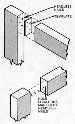
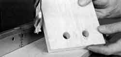
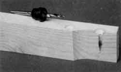
Other methods may be used according to the job and the number of pieces to be drilled. Templates may be made of illustration board, hardboard, plywood, or metal, depending on how long they will be used. Some pieces of hardware are their own templates, for example, a hinge or a drawer pull.One little trick that should be remembered for use on mating pieces, when ordinary layout may be impractical or time-consuming, is to insert headless nails in small holes drilled in one of the pieces Figure 7-5. Let the points protrude about 1/16″ and then press the piece against the mating part. The nail points will mark the hole locations on the second piece. Pull the nails with a pair of pliers and drill the holes to full size.
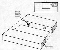
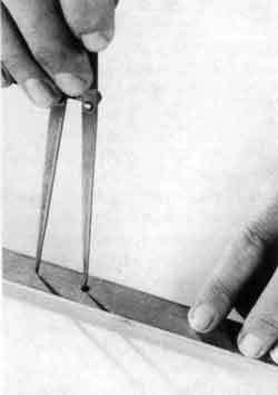
Another method of marking jointing members (especially when employing dowels) is to use dowel center finders Figure 7-6. After drilling the holes for the dowels in one piece of wood, you insert dowel centers in these holes. Then you align the two pieces of wood as they will be joined. When you press them together, the points on the dowel centers mark the second piece of wood. It is now possible to drill holes at these center marks. When the pieces are connected with dowels, the blind dowel joint is perfectly aligned. Dowel centers commonly come in assorted sizes to fit holes from 1/4″ to 1/2″ in diameter. For larger holes, a dowel rod with a brad in the center works well.
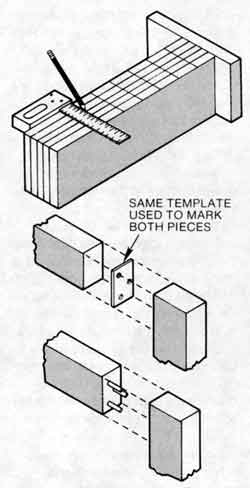
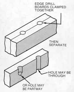
Figure 7-7 illustrates two methods of marking hole locations when boards are to be joined edge-to-edge by doweling.
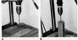
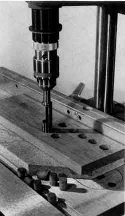
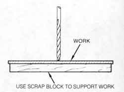
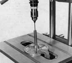
Supporting The Work
When drilling through holes place a scrap block between the workpiece and the table Figure 7-8. This protects the table and lets the bit point cut through into the scrap block so that it does not splinter the back of the workpiece as it emerges. Warning: Clamp the workpiece to a supporting surface to keep the bit from grabbing in the hole and jerking the workpiece out of your hands, particularly when the point is about to break through.
Use of the rip fence or miter gauge as a guide and support will lessen the need for clamping. When the workpiece being drilled is held against the rip fence or miter gauge, the twisting force exerted by the bit is taken by the fence or miter gauge and not by your hands.
The grain on some woods, such as fir, may pull a bit off center. When this happens, try clamping the work, drilling a small pilot hole, and then enlarging the hole to full size by drilling halfway through from each side.
General Drilling
There are two basic types of holes: holes that you drill completely through the workpiece and holes that you drill only partway through the work piece.
Drilling Through
Mount the rip fence on the worktable. It will be used as a backstop. Adjust the rip fence to help you accurately position the hole where you want it. Make fine adjustments with the table height lever (Model 500) or crank (Model 510) Figure 7-9. If there’s no room for the rip fence, use the miter gauge. Caution: Place a scrap of wood, wider than the workpiece, on the table to keep the bit from drilling into the table after it goes through the workpiece. It will also help keep the workpiece from splintering where the bit exits.
Hold the carriage so that it won’t drop against the base mount. Loosen the carriage lock and adjust the table height so that the tip of the bit is 1/4″ to 1/2″ above the workpiece. Then tighten the lock.
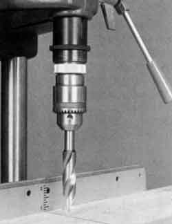
Extend the quill so that the tip of the bit touches the scrap block. Set the depth control to approximately 1/8″, and tighten the depth control lock Figure 7-10. Then retract the quill. When you drill the hole, the depth control will keep the bit from biting through the scrap block and into the worktable.
Make a five-point check. Four of the five locks–power plant, carriage, table height, and table tilt–should be secure. The quill lock should be loose.
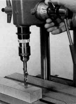
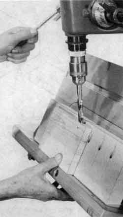
Place the workpiece on the worktable and position it under the bit. Hold it firmly against the table and rip fence. Extend the quill with the machine turned off to be sure the bit will drill a hole right where you want it Figure 7-11.
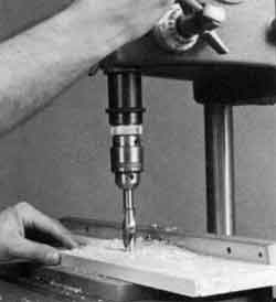
If the bit lines up correctly, turn the Mark V on and adjust it to the correct running speed. Feed the bit into the wood slowly and evenly Figure 7-12. Don’t force the bit; just maintain a light, steady pressure. When drilling deep holes, it is necessary to retract the bit now and then to clear chips from the hole.
When you feel the depth control stop the quill, retract the bit. Turn off the machine, let it come toa stop; then remove the workpiece.
Avoiding Tear-out–Tear-out, the rough, splintery edges where the bit exits the workpiece, can be avoided by moving the scrap block every time you drill a new hole, so there’s always a flat, firm surface to back up the workpiece. Or, if you’re using brad-point bits, you can use the depth control to avoid tear-out.
With the Mark V turned off, extend the quill until the pilot of the bit touches the scrap board. Set the depth control to “0” and lock it in place. Let the quill retract
Drill the holes you need, letting the depth control stop the quill. Turn off the Mark V and turn the workpiece over. There will be tiny pinholes where the pilot started to come through the workpiece Figure 7-13. Use these pinholes to line up the bit; then finish drilling the hole from the other side. Since brad-point bits have spurs that cut the wood grain smoothly when they enter the wood, there will be no tear-out on either side of the workpiece.
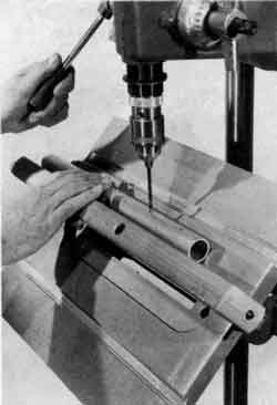
Drilling Partway
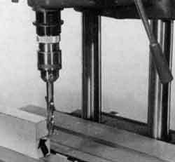
To drill a hole only partway through a workpiece, extend the quill until the cutting flutes of the bit just touch the workpiece Figure 7-14. Set the depth control at the desired depth and lock it in place; then drill the holes you need.
The depth control will stop the quill when the bit reaches the proper depth in the stock. All the holes you drill at any one depth control setting will be exactly the same depth.
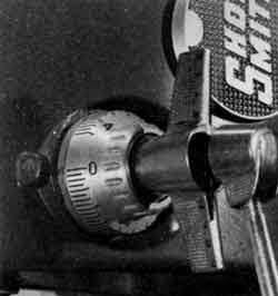
Another way of drilling partway is to mark the work to indicate the necessary hole depth. Extend and lock the quill so the point of the bit lines up with the mark on the work Figure 7-15. With the quill held in the extended position, rotate and lock the depth control at “0” Figure 7-16. Unlock the quill and proceed with the drilling.
Drilling Screw Holes
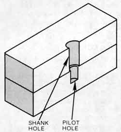
If screws are to drive easily and hold with maximum strength, the screw holes must be drilled carefully and to size (Table 7-2). Usually two holes are needed: the shank hole, which equals the screw diameter, and a smaller pilot hole, which allows the screw end to penetrate the wood Figure 7-17.
| Table 7-2: Drill Bit Sizes for Screws | |||
| Screw Gauge Number | Shank Hole (Hardwood & Softwood | Pilot Hole (Softwood) | Pilot Hole (Hardwood) |
| 0 | 1/16 | 1/64 | 1/32 |
| 1 | 5/64 | 1/32 | 1/32 |
| 2 | 3/32 | 1/32 | 3/64 |
| 3 | 7/64 | 3/64 | 1/16 |
| 4 | 7/64 | 3/64 | 1/16 |
| 5 | 1/8 | 1/16 | 5/64 |
| 6 | 9/64 | 1/16 | 5/64 |
| 7 | 5/32 | 1/16 | 3/32 |
| 8 | 11/64 | 5/64 | 3/32 |
| 9 | 3/16 | 5/64 | 7/64 |
| 10 | 3/16 | 3/32 | 7/64 |
| 11 | 13/64 | 3/32 | 1/8 |
| 12 | 7/32 | 7/64 | 1/8 |
| 14 | 1/4 | 7/64 | 9/64 |
| 16 | 17/64 | 9/64 | 5/32 |
| 18 | 19/64 | 9/64 | 3/16 |
| 20 | 21/64 | 11/64 | 13/64 |
The easiest procedure is to drill the shank hole first. This establishes a guide and a center for the pilot hole. Countersinking, which can be controlled by using the depth control, is done on the surface to establish a seat for the head of the screw when it must be flush with the surface of the work Figure 7-18. In softwoods or when the head of the screw is small enough, countersinking may be eliminated since the screwhead will form its own seat as it is turned into the wood.
Screw and bolt holes can be counterbored when it is desirable for the fastener head to be set beneath the surface of the wood.
Counterbored holes are often sealed with plugs cut from the same type of wood. These may be set flush with the surface of the work and glued in place so the grains match, or they can protrude slightly to provide a decorative touch. This is seen quite often on Early American furniture.
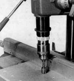
Special bits, like the screw bit shown in Figure 7-19, let you drill accurate screw holes with minimum fuss. They are actually bits that form tapered holes and have sleeve-type, adjustable counter-sinks and collars so you can control hole depth and countersink diameter.
Drilling Holes Through Extra-Thick Stock
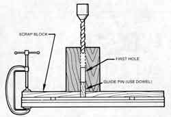
Because a spindle extension has a limit and bits should not be buried in the work more than the length of the bit’s flutes, it isn’t possible to drill through extra-thick stock in normal fashion. You must drill from both sides of the stock. The problem is that it is difficult to drill both holes on the same center line; the solution is to use a guide that correctly positions the work after the first hole is drilled.
One method is shown in Figure 7-20. After the first hole is drilled in the work, clamp a piece of scrap to the table and drill through it. Insert a hole-sized piece of dowel in the scrap piece, replace the work so the first hole drilled will be over the dowel, and finish drilling.
Another method calls for a special insert Figure 7-21A, one you can retain for future, similar operations. The drilling procedure is the same. Drill the hole as deeply as you can, or a little more than halfway through the stock. Then position the work by placing it over the pin in the insert and finish drilling Figure 7-21B.
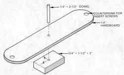
Make the special insert like the one detailed in Figure 7-22. Drill the hole for the guide dowel after the insert is assembled and locked in the table. Thus, alignment of the bit to the guide dowel will be assured.Drilling Extra-Large Holes
Large diameter holes, can be formed using special cutters such as hole saws Figure 7-23. Hole saws are heavy steel cups with small saw teeth on the perimeter. They mount on mandrels that have a shank that can be gripped by the drill press chuck. One mandrel is usable with several sizes of hole saws.
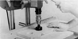
Start the operation at the proper speed recommended by the manufacturer and slowly increase feed pressure until the saw is cutting smoothly and without binding or burning.Plug Cutting
As mentioned earlier in the chapter, the best method to conceal screwheads so they don’t spoil the appearance of a project is to counterbore for them and then fill the hole with a wooden plug. Often, the hole is filled with a short length of dowel or a commercial, preformed plug.
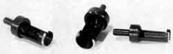
Both ideas work; however, the items are available only in limited wood species and it’s often impossible to match the grain pattern of the plug and the work. The solution is to make your own plugs by working with plug cutters like those shown in Figure 7-24. With these, you can cut into the edge or end of stock and not only use a matching wood, but also control the grain pattern. Plug cutters are available in the sizes shown in Table 7-3.
| Table 7-3: Plug Cutter Sizes | |
| Plug Cutter Size | For Screw Sizes |
| 3/8″ | #8, #9, #10 |
| 1/2″ | #12, #14 |
| 5/8″ | #16, #18 also for bolts up to 1/4″ |
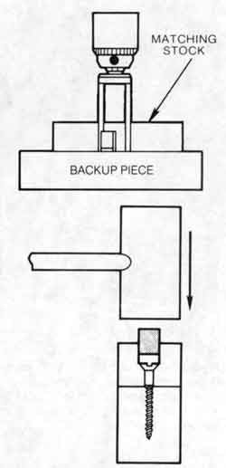
A basic procedure is shown in Figure 7-25. Drill through the stock and remove the plug. Cut the plug about 1/16″ longer than needed with a bandsaw, scroll saw or hand saw. Coat the plug with a little glue, match the grain, and then drive it into the counterbored hole. After the glue is dry, you can sand the plug flush or allow a bit of itto project as a decorative detail.Another type of plug cutter, shown being used in Figure 7-26, can be used like the first ones mentioned but can cut deep enough to form plugs, or short dowels, up to 2″ long. Thus you can use them to form custom dowels for edge-to-edge joints and even to shape axles for small toy projects. Work as shown in Figure 7-27 when you want the wood grain to run in the plug’s long dimension. After the plugs are formed, they can be separated by making a cut on the bandsaw or table saw.
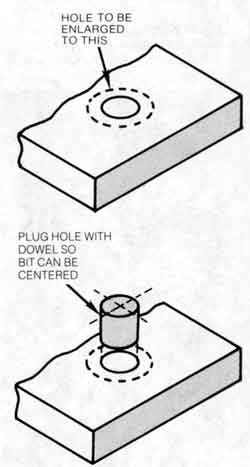
An interesting use for plugs is shown in Figure 7-28. If you have made a mistake locating a hole or simply wish to enlarge a hole, fill it with a plug so you can establish a center for the new hole.
To drill a hole at any angle between 45° and 90°, simply tilt the table. When the table is tilted, mount the rip fence on the “down” side of the table (Figure 7-29) or use clamps. This will give the workpiece the maximum support.
Angular holes in round work require an arrangement that keeps the work from turning while the hole locations have the same edge distance and are on a common centerline. V-blocks and stock are usually clamped to the table so the work can’t be turned. Since the miter gauge can be locked in the table slot, it may be used together with a straight piece of wood to improvise a V-block that permits accurate drilling (Figure 7-30). The same type of setup can be used to drill angular holes in square workpieces (Figure 7-31).
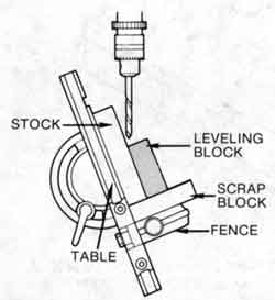
It is good practice to work with a leveling block when the angle you need is sharp (Figure 7-32). On such work, the side of the bit may contact the work before the point does. This can cause the bit to drift off center. The block, when it is used as shown in Figure 7-33, establishes a center for the bit even before it touches the work, thus assuring that the hole location will be correct.
V-Block Drilling
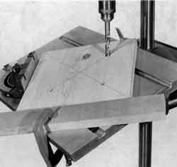
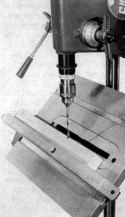
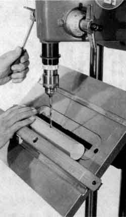
The table and fence can be situ-ated as shown in Figure 7-34 when you need to drill diametrically into or through round material. Tilt the table to 45° and then adjust it and the fence position so the point of the bit will exactly bisect the “V.” If you need more than one hole on the same centerline, mark the workpiece so the bit point can be correctly positioned each time. For through holes, line the “V” with lengths of scrap wood. The same setup and procedure can be used when you need to drill holes in the corners of square stock (Figure 7-35). Make the initial contact slowly and carefully so the bit won’t move off center.
Drilling Using Special Setups
Whether you are doing production work or simply wish to reduce layout functions on a single piece while still achieving accuracy, you can work with setups using Mark V accessories or others that you invent to suit a particular application.
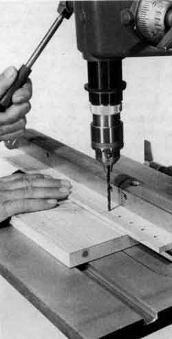
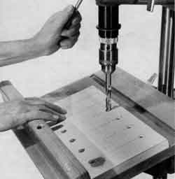
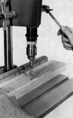
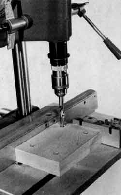
A basic setup, one that is needed quite often, is demonstrated in Figure 7-36. The job calls for a series of holes on a common centerline to have the same edge distance. The work is marked for hole spacing; the fence is adjusted for the edge distance. When adjusting the fence, lock it in an approximate position and then use the table height lever (Model 500) or the table height crank (Model 510) as a forward feed mechanism to make the final adjustment. When holes with the same edge distance are required on both edges of the stock, all you have to do to drill the second set of holes is turn the work so its opposite edge is against the fence.
In some situations, the rip fence and the miter gauge are used together (Figure 7-37). Because of the special screw and slot in its bar, the miter gauge’s position can be secured without the use of clamps.
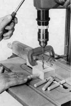
Even small pieces, like round pieces of dowels, can be organized for similar drilling on any number of pieces. The drill hole and the dowel accommodation hole are bored on the same centerline. You are then assured that the hole in each piece will be centered and will have the same edge distance (Figure 7-38).
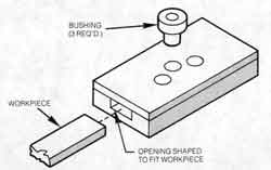
Another example of a hole locat-ing setup is shown in Figure 7-39. The design depends, of course, on the work that must be done. Using bushings will assure that the guide hole or holes will not become dis-torted by repetitive drilling.
Using a Hole-Spacing Guide
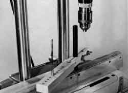
If you make the hole-spacing guide that is shown in Figure 7-40, you will be able to accurately drill a series of equally spaced holes, all with the same edge distance, without having to do layout work. The fence is locked in approximate position and the table is adjusted so drilling will occur on the centerline of the workpiece. After the first hole is drilled, the guide is adjusted so the guide pin will engage that hole and position the workpiece for the next hole. The procedure is then repeated-drill a hole, lift the guide pin so you can reposition the workpiece, insert the guide pin in the last hole, and position the workpiece for the next hole (Figure 7-41).
The guide is made by following Figure 7-42. The large holes are for the post-either the mortising holddown post or 5/8″ diameter bar stock-that is secured to the rip fence (Model 500) or a fence extension with a hole drilled in the top (Model 510). The small holes are for the guide pin. The guide pin is 1/4″ dia. so you can only drill 1/4″ dia. holes, but this is not a limitation. If you need larger holes, mount the proper size dowel to the end of the guide pin to enlarge it to the proper size.
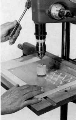
Indexing
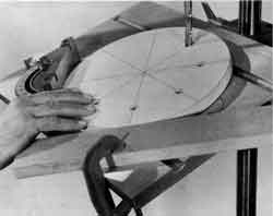
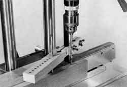
When you need holes that must be equally spaced around a circumference and have the same distance from a center, you can work accurately by using a pivot guide as shown in Figure 7-43. The guide is a table slot size strip of wood with a small nail driven through it that projects just enough to seat in the stock. The guide is clamped in place and the table is adjusted so the distance from the pivot to the center of the bit equals the radius you need. The distance between holes is determined by laying out equally spaced segments. Caution: If the project calls for through holes, mount a piece of plywood to the guide strip to back up the bit.
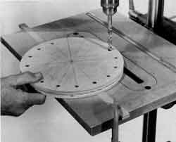
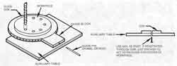
Another option is to make an indexing device (Figure 7-44). The guide disk has equally spaced holes around its edge so it can be turned a specific amount and held there by the guide pin that passes through the guide block. Since the work piece turns with the disk, the holes you need will also be equally spaced. Caution: When the holes must be drilled through the work piece, mount a scrap backup to the indexing device.
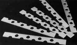
Drilled Moldings
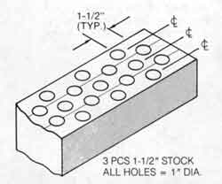
You can produce interesting and original moldings if you follow the procedure demonstratea Dy me following example. Clamp together three pieces of 1-1/2″ thick stock and draw a layout for holes as diagrammed in Figure 7-45.
After the holes are drilled, separate the three pieces and strip-cut each one on the table saw or bandsaw so you end up with individual pieces like those in Figure 7-46. Saw with a smooth cutting blade so the pieces will be smooth without needing a lot of sanding.
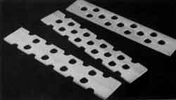
The parts you produce can be used individually or they can be assembled edge-to-edge to make interesting panel designs (Figure 7-47). Try some experiments with how you strip-cut the pieces after they are drilled. For example, instead of sawing with the stock flat so you cut across the holes, make cuts with the stock on edge. By planning the saw cuts and then joining particular pieces, you can produce intriguing patterns like the one shown in Figure 7-48.
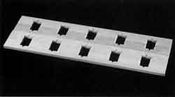
You can also vary designs by drilling different size holes and by changing hole spacing. The same drilling technique can be used to produce semi-circular grooves (Figure 7-49).
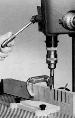
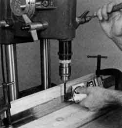
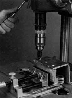
Metal Drilling Layout
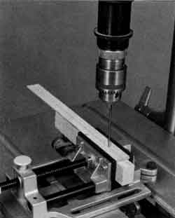
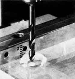
Metal drilling requires a firm support as close to the cutting area as possible (Figure 7-50). Warning: The workpiece should always be clamped or gripped in a device such as a drill press vise or locking pliers. Backup scrap should be used so the torque of the bit, as it breaks through, does not jerk the metal.
When drilling metal, set the speed to the maximum recommended or slower and use a sharp, high-quality twist bit. To determine the maximum recommended speeds for various metals, use the following formula: high-quality twist bit. To determine the maximum recommended speeds for various metals, use the following formula: Caution: Feed the bit very slowly into the workpiece and apply plenty of oil to the tip of the bit while you’re drilling. This will keep the bit from dulling (Figure 7-51).
If the bit catches, back it out quickly; then feed it more slowly with less pressure. If the bit stalls completely and the quill won’t retract, quickly turn off the Mark V. Back the bit out of the hole, turning it counterclockwise by hand. Once the bit is free, turn on the machine and feed the bit very slowly back into the workpiece. Once the bit goes through the workpiece, turn off the Mark V and let it come to a complete stop before you remove the workpiece.
Metal Drilling Layout
A scriber is usually used for marking metals, but often the line won’t show clearly unless you bear down on the scriber. Since this might scratch the material more deeply than desired, special dyes are used to coat the metal (Table 7-4). Apply the dye coater. Don’t “paint” the metal; a thin but even coat is sufficient. Allow it to dry then scribe the lines. The scribe lines should be just light enough to remove a tiny thread of the coating and thus reveal the metal beneath. The metal itself is not harmed. Warning: Prepare the dyes care-fully. Always follow safety cautions that may be on the container of the material you use.
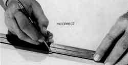
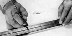
When marking a dimension point, don’t place the scale flat on the work and then scratch with the scriber to form the mark (Figure 7-52). A precise method is shown in Figure 7-53. Set the scale on its edge and then run the point of the scriber down the graduation groove. This will leave a fine dot as a dimension point, which is all you need.
| Table 7-4: Surface Coaters | |
| Materials | Dye |
| Rough Metals | White or blud chalk, rubbed on surface. |
| Castings | Whiting (mixture: 50-50 white lead and turpentine). |
| Smooth Steel | Copper sulfate (2 tablespoons in 1 cup water – crysatls available at drugstores or chemical house) or layout compound (purple coating, available at hardware store). |
| Bright Sheet Metal | Layout compound. |
| Warning: Prepare the dyes carefully. Always follow the cautions that may be on the container of the material you use. | |
| NOTE: You can keep layout dye in a discarded shoe polish bottle – one with dauber which may be used to apply the dye. Apply dye evenly and smoothly on the surface of the metal. Don’t paint the metal; a thin, even coat is sufficient. |

An angle gauge or similar marking tool (Figure 7-54) can be used as an edge-marking gauge when you need a line parallel to the edge or end of a piece of work. Maintain the scriber’s contact as you move the gauge along. Dividers can be used to gauge the distance between holes (Figure 7-55) or to mark the locations of equally spaced holes.
Drilling Preparations
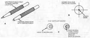
After hole locations have been established, a prick punch is used to mark the hole’s center. The prick punch has a slender, sharp point which is easy to place at the correct drilling spot. The small spot it makes is enlarged with a center punch, which forms a small well that serves as a seat for the point of the bit (Figure 7-56A).
Positive accuracy, especially when drilling large holes, is assured by using the method shown in Figure 7-56B. After the hole location has been prick-punched, scribe a circle the same size as the hole you want, or a bit larger, around the center mark. The scribed circle is a guide that will reveal any tendency of the bit to drift off center.
A way to work, should the bit start to drift, is shown in Figure 7-56C. Make a series of small chisel or prick punch marks as the illustration shows; then continue drilling.
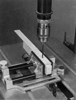
Centering Pin Use
A precise way to position work so the hole location will be centered with the bit point is to use a centering pin (Figure 7-57). The pin itself is a short length of 1/8″ or 1/4″ steel rod, sharpened to a fine point at one end. The work is gripped in a holding device, in this case a drill press vise, and is positioned indentation made with the prick punch. Clamp the vise firmly in place; then do the drilling after substituting the bit for the pin (Figure 7-58).
The drill press vise is a unique tool in that it is easily bolted to the worktable. The replaceable jaws have vertical and horizontal V-grooves so they can securely grip round stock, triangular pieces, and flat material.
Concentric Drilling
A drill press vise is commonly used to hold short pieces of round bar stock vertically for concentric drilling. But, a unique and practical way to work, if stock diameter permits, is to use a lathe faceplate as shown in Figure 7-59. An advantage is assurance that the stock will be in true, vertical position. Place the faceplate on a flat surface as you insert the stock and secure it with the faceplate’s locking setscrew.
V-Block Drilling
The combination of the rip fence and table as a V-block works for woodworking as well as metal-working. With the table tilted 45° and the fence secured, perfect support is created for drilling round stock (Figure 7-60).
Be sure that the setup is situated under the spindle so the bit meets the work at its highest point, which is the centerline of the work. Caution: If the hole is to go through the stock, use scrap wood under the work to protect the table and fence.
Machine screws and stove bolts often have countersunk heads, so they need a seat in the work if they are to be flush with work surfaces. Countersinking is done after the holes for the fasteners have been drilled. As with all metal work, be sure the workpiece is secure in a holding device and that the holder is clamped to the table (Figure 7-61).
Countersunk heads on stove bolts and machine screws have a different angle than those on wood screws, so be sure to use a countersink designed specifically for metalwork.
Spot Polishing
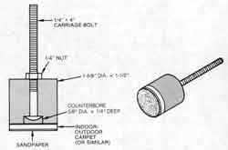
Spot polishing, or “damaskeening,”is an attractive finish easily accomplished on soft metals by working as shown in Figure 7-62. The spot-polishing tool being used is made by following the plan in Figure 7-63. The final appearance of the finish will depend on the uniformity of the application and how much you overlap the spots. Use a backup block under the work and set the rip fence so each set of spots will have a common centerline.
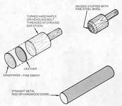
You’ll be able to judge immediately, by checking the first spot, just how much feed pressure you should use. Figure 7-64 shows some other types of spot-polishing tools you can make. When abrasive paper or steel wool is used to abrade the spots, the work is done dry. If a straight rod is used, a mixture of emery dust and light oil is used on the work. The turning rod causes the mixture to abrade the metal which, in turn, causes the spot to appear.
Drilling Plastic
When drilling plastics, work at a fairly slow speed, between “Slow” (700 RPM) and “0” (1050 RPM). The larger the hole, the slower the speed should be. If you go too fast, the bit will heat up and melt the plastic.
Don’t use brad-point bits; you will dull them. You can use a twist bit, but you risk splintering certain types of plastic. The best bit is a special plastic-drilling bit. These bits have a tip ground at 60° for a smoother cut in plastic Figure 7-65. Warning: Do not use twist bits to drill plastics. They will splinter certain types of plastic.