When the Mark V is set up in the horizontal boring mode, it becomes a machine that enables you to do a variety of standard and specialty operations easily and with great accuracy. It allows you to make holes in large or long pieces that you ordinarily couldn’t drill. It also simplifies a number of other operations normally performed with a hand-held drill, such as drilling end grain or doweling boards edge-to-edge.
Setup and Features
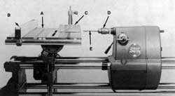
Use the accessories shown in Figure 11-1 for boring operations. To set up your Mark V in the horizontal boring mode, follow the instructions in the Owners Manual that came with your machine.
As you work in the boring mode, you’ll find that the Mark V is an extremely capable horizontal boring machine. It has the same features as the drill press mode plus these special features:
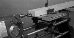
With a 5-1/2″ long bit mounted in the chuck and using the rip fence as a backstop, you can bore workpieces up to 30″ long or wide (Model 500) or 55″ (Model 510 with the extension table system). Without the rip fence, you can bore as large or wide a workpiece as you can safely and easily control (Figure 11-2).
With the table tilt at “0” and the table height as low as it will go, the table drops 2-3/8″ beneath the center of the main spindle. This allows you to bore to the center of stock up to 4-3/4″ thick.
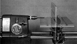
The table tilts from 90° left to “0” in this mode (Figure 11-3).
Horizontal Boring Safety
Warning: Before using the horizontal boring machine, read and understand these important safety instructions:
Danger Zone-The danger zone on the Mark V in the horizontal boring mode extends 3″ all around the bit and chuck and 5″ in front of the bit. Always keep your fingers and hands out of the danger zone.
When you work at the horizontal boring machine, be certain your hands and fingers aren’t in front of the bit when you advance the quill. Never reach in toward or in front of the bit to clear away scraps. Turn off the machine and let it come to a complete stop first.
- Wear proper eye and ear protection.
- NEVER leave the key in the chuck. Remove the key from the chuck IMMEDIATELY after securing or removing the bit.
- Never wear jewelry, gloves, ties, loose clothing or clothing with long sleeves. Keep long hair tucked under a hat. Jewelry, gloves, ties, clothing and hair could become entangled in the bit.
- Use the rip fence as a backstop and hold the stock firmly against both the worktable and the fence. If you can’t use the rip fence, use the miter gauge or clamp the stock to the worktable.
- Use only accessories and bits designed to be mounted in power drills.
- Never drill or bore metal freehand. Always clamp the metal to the worktable and backup stock, or the rip fence and back-up stock.
Bits and Speeds
Because boring is so similar to drilling, you can use the same bits and the same speeds. To adjust the Mark V to the correct speed, refer to Table 11-1.
| Table 11-1: Horizontal Boring Speed Chart | ||
| Size of Hole | Hardwood | Softwood |
| 1/4″ and less | H (1600 RPM) | I (1750 RPM) |
| 1/4″ to 1/2″ | F (1300 RPM) | G (1450 RPM) |
| 1/2″ to 3/4″ | D (1050 RPM) | E (1150 RPM) |
| 3/4″ to 1″ | B (850 RPM) | C (950 RPM) |
| Over 1″ | SLOW (700 RPM) | A (750 RPM) |
| Boring metals (twist bits only)-Slow (700 RPM) | ||
| Note: These speeds are for 60 hz. operations. For 50 hz. operations, refer to Table 1-1. |
General Boring
As you might suspect, the procedure for boring is very similar to the procedure for drilling. The basic types of boring operations are also similar–you can either bore all the way through a piece or part way into it.
Boring Through
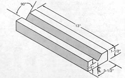
To bore through stock, first mount a bit in the chuck. Be sure that you remove the chuck key. Mount the rip fence on the table to use as a backstop, and adjust it so that it will hold the workpiece 1/4″ to 1/2″ away from the tip of the bit. To accurately position the hole, adjust the table height. Caution: Place a long scrap of wood against the rip fence to keep the bit from boring into the fence after it goes through the workpiece. This scrap should be 3/4″ to 1″ thick and taller than the workpiece to properly back up the piece when boring.
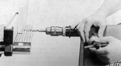
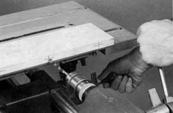
Extend the quill so that the cutting flutes of the bit touch the scrap wood. Set the depth control to approximately 1/8″, and tighten the depth control lock (Figure 11-4). Then let the quill retract. When you bore the hole, the depth control will keep the bit from biting through the scrap and into the fence.
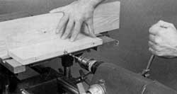
Stand at the front of the machine so that you can easily reach the power switch. Place the workpiece on the table and position it in front of the bit. Hold it firmly against the table and rip fence. Extend the quill with the machine off to be sure the bit will bore a hole right where you want it (Figure 11-5).
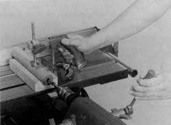
If the bit lines up correctly, retract the quill. Turn the Mark V on and set the speed dial. Feed the bit into the wood slowly and evenly (Figure 11-6). Don’t force the bit; just maintain a light, steady pressure as you do when drilling. When boring deep holes, it may be necessary to retract the bit occasionally to clear chips from the hole.
When you feel the depth control stop the quill, retract the bit. Turn the speed dial to “Slow”, turn off the machine and let it come to a complete stop, then remove the workpiece.
Boring Part Way
To bore a hole only part way through a workpiece, extend the quill until the cutting flutes of the bit just touch the workpiece. Set the depth control at the desired depth and lock it in place. Bore the holes you need. The depth control will stop the quill when the bit reaches the proper depth in the stock. All the holes you bore at any one depth control setting will be exactly the same depth. Note: When you need to bore a number of holes all at the same height (doweling boards edge-to-edge) on Model 500, use an accurate centerline as a guide.
Boring End Grain
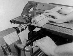
When boring end grain, use the miter gauge to align the workpiece with the bit. Adjust the safety grip to the thickness of the stock. Note: When boring end grain, adjust the speed one to two letters slower than you normally would. End grain is much tougher than edge grain.
If the workpiece is less than 30″ long (Model 500) or 55″ long (Model 510), mount the rip fence on either the table or the extension table and use it as a backstop. If the piece is longer than 30″ or 55″and you have to work without a backstop, clamp the workpiece to the table.
Adjust the table height and depth control as desired, make a four-point check. The power plant, carriage, table height and table tilt locks must be secure. As you feed the bit, don’t be alarmed if it takes more pressure than usual to bore the hole.
Boring At An Angle
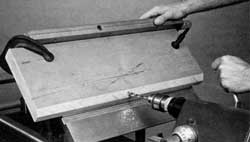
To bore a hole at an angle, simply tilt the table at any angle you desire, from 900 left to “0,” in toward the power plant. If possible, mount the rip fence on the table and use it as a backstop(Figure 11-7). If the workpiece is very large, you’ll have to clamp it to the table to prevent it from slipping. Caution: If the angle is acute and you’re boring through the workpiece, remember to protect both the table and the rip fence with a scrap block.
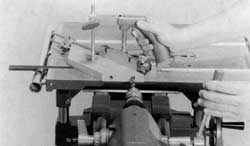
nother way to bore at an angle, is to use the miter gauge. Figure 11-8 shows boring at an angle using the miter gauge stop rod to keep the bit from pushing the stock out of alignment.
Boring For Dowels
Dowels are often used to reinforce various types of joints. They even sometimes substitute for the mortise and tenon joint. A more routine application is reinforcement with dowels when narrow boards are joined edge-to-edge to form wide workpieces. The combination of worktable surface, rip fence, and depth control makes the hole-boring operation purely mechanical. The edge distance of the holes is established by table height. The holes do not have to be exactly centered, but must be in line with each other. Mark the bad surface of each piece and be sure it faces up when you bore.
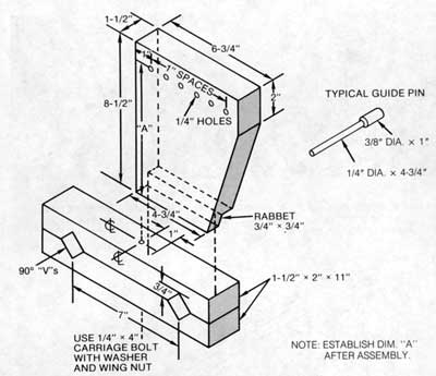
Hole spacing can be controlled automatically if you make the hole-spacing guide that is shown in Figure 11-9. The important part of the construction is getting the guide pin holes exactly on the bit’s horizontal centerline. To determine dimension “A”, assemble the guide and secure it to the way tubes. Then, with a bit secured in the chuck, advance the quill so the point of the bit will mark the guide. Use a square to mark this point across the guide and, on this line, bore the holes for the guide pin.
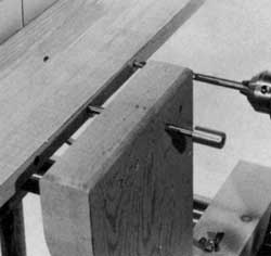
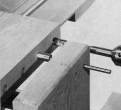
When you use the guide, the guide pin engages the last hole that was bored and so positions the workpiece for the next hole (Figure 11-10). Hole spacing is variable because of the set of holes in the guide and, since the guide pin has a 3/8″ diameter bushing at one end (Figure 11-11), you can bore either 1/4″or 3/8″ holes. By making an assortment of guide pins, you can set up the guide for boring holes of whatever diameter you wish.
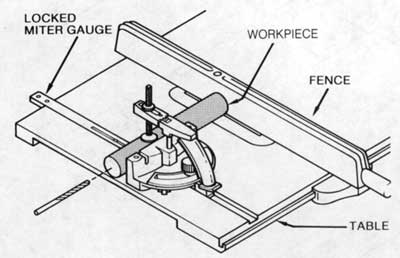
Boring Dowel Holes in Miters– Miter joints are often strengthened with dowels. The important factor is for the holes to enter at right angles to the cutline. The miter gauge holds the workpiece at the correct angle; the rip fence, with a spacer attached, is set to suit the length of the workpiece. The miter gauge safety grip holds the workpiece securely in position as the hole is bored. When the workpiece is extra-long, use the miter gauge to hold it at the correct angle and a clamp to secure it to the table (Figure 11-12).
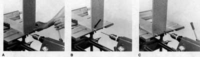
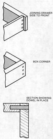
This is an excellent joint to use on drawer front to drawer side connections since it has the characteristics of the dovetail, but it is much easier to accomplish. First, cut the side and front of the drawer to size and then set the pieces in position as shown in Figure 11-13A. The miter gauge positions the work square to the spindle; the fence acts as a backup; and the table height is adjusted for edge distance. Bore the first hole and insert a dowel in it (Figure 11-13B) so the parts will be held in correct position for the holes that follow (Figure 11-13C). This method can be used for box corners as well as drawers (Figure 11-14).
Boring Odd Shapes
An odd-shaped piece, like a curved segment, can be set up for boring by simply positioning it correctly and then clamping it in place on the table. However, if you have many similar pieces to bore, you can make a guide that will place each piece in exactly the right position. This lets you work more accurately since it eliminates the possibility of human error. An example guide, shown just to demonstrate the concept, is shown in Figure 11-15.
Pivot Boring
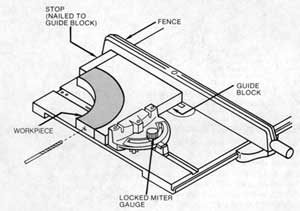
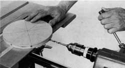
Radial holes into the edge of circular workpieces can be bored accurately by working as shown in Figure 11-16. This procedure is known as pivot boring. A strip of wood, sized to fit the table slot and with a short nail driven through it at an approximate midpoint, is clamped to the table so the nail is aligned with the spindle’s center. The workpiece, marked off in degrees for the holes that are required, is centered over the pivot nail and rotated to position it for each hole. Set the depth control to limit quill extension.
Concentric Boring
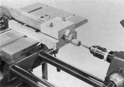
A round or a square workpiece, if it is not too long, can be positioned for accurate concentric holes by using the miter gauge and the fence as shown in Figure 11-17. The table height is adjusted so the drill point will be on the workpiece’s horizontal centerline. The miter gauge, locked in place, maintains the workpiece’s alignment; the fence serves as a backup.
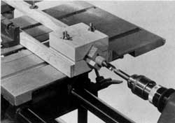
Another method requires the use of a V-block (Figure 11-18) which cradles the workpiece as demonstrated in Figure 11-19. When the workpiece is shorter than the V-block, use a length of scrap wood between the workpiece and the fence. The V-block can also be used to hold square workpieces (Figure 11-20).
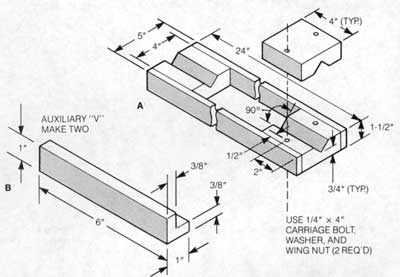
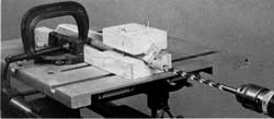
For extra-long workpieces, use an extension V-block as shown in Figure 11-21. The V-block is also used to grip short workpieces (Figure 11-22). The V-block, held in place by being clamped to the locked miter gauge or clamped to the extension table, is positioned so the vertical centerline of the spindle bisects the “V.” Table height is adjusted in relation to the diameter of the workpiece. Small auxiliary V’s are used when the workpiece is too small to be gripped by the basic V-block. Figure 11-23 shows how the extension V-block and the auxiliary V’s are made.
Boring Extra-Deep Holes
Holes that are deeper than you can form by using a conventional bit can be bored with an extension bit (Figure 11-24), a special tool that in many cases is no more than a regular drill bit that has been brazed onto a rod. The procedure is to bore to the quill’s maximum extension and then, after retracting the quill, to move either the table or the power plant so the drill will reach the bottom of the hole. Thus you can deepen the hole by again extending the quill. Since the rod part of the extension doesn’t have flutes, you must retract frequently to clear waste chips from the hole.