Although lathe turning is often considered one of the most creative and rewarding types of woodworking, it can also be one of the most frustrating–especially for the new or inexperienced woodworker. That’s because many projects require several matching pieces-such as two lamps, four table legs or a set of salad bowls–and it usually takes quite a bit of practice to develop the necessary skills to turn these matching pieces by conventional methods.
The lathe duplicator eliminates this problem and makes it possible for anyone to turn as many duplicate pieces as they need after only one or two short practice sessions. In addition, the duplicator allows you to enjoy the lathe and create freehand turnings without having to learn how to hold, use or sharpen ordinary lathe chisels.
These capabilities are possible because of the lathe duplicator’s unique design. Instead of using ordinary chisels, the duplicator has cutters which are mounted securely to a separate tool rest assembly. A follower with the same profile is installed directly above the cutter. By guiding the follower along a template or pattern mounted above the stock, the cutter will duplicate the profile in the workpiece below.
Setup and Features
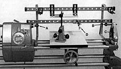
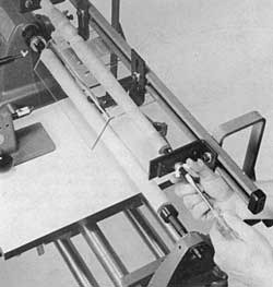
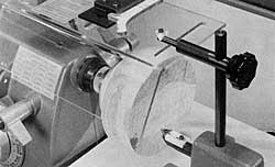
The lathe duplicator mounts on the Mark V Models 500 and 510 (Figure 13-1). To set up the lathe duplicator follow the instructions in the Owners Manual that came with the duplicator.
Some of the important features and capacities of your lathe du-plicator are:
- Maximum spindle length
– 34″ with cup center
– 33-1/2″ with live center and no spacer
– 32″ with live center and 1-1/2″ spacer - Minimum spindle length
– 6-1/4″ with cup center
– 5-3/4″ with live center and no spacer
– 4-1/4″ with live center and one spacer
– 2-3/4″ with live center and two spacers - Maximum spindle diameter
– 8″ for freehand turning or with flat template
– 4″ with an original turning as a template - Maximum bowl diameter
– 8″ for freehand turning or with flat template - Maximum depth of cut
– 2-1/4″ for duplication (up to 3-1/4″ for light freehand cuts inside bowls) - Template specifications
– 36″ maximum length
– 3/8″ maximum thickness
– 1/4″ minimum thickness (smaller templates only)
Critical Alignments
Proper alignment is important for all power tools, but accuracy is especially important with the lathe duplicator. Even a small error in alignment will cause a variation in the duplicated pieces.
Complete alignment instructions are provided in the Owners Man-ual that came with your duplicator. The four most critical alignment procedures are summarized below. These alignments should be checked whenever the lathe duplicator is set up or if problems occur when making duplicates.
Cutter Support Alignment
In order to cut properly, the cutter support must be aligned so that the top of the cutter tip is held parallel to the surface of the worktable.
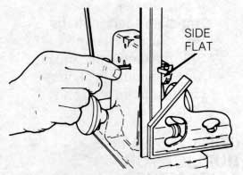
Begin by removing the follower support. Then loosen the nylon cutter guide and slide it back to expose the flat side of the cutter support rod.
Loosen the front and rear cutter support setscrews and adjust the center setscrew so it is lightly seated in the positioning groove of the cutter support rod. This assures proper protrusion of the cutter tip relative to the follower tip during duplication.
Place an accurate square on the tool rest base and adjust the cutter support, so that the side flat is against the square as shown in Figure 13-2. Then tighten the setscrews, reposition the cutter guide and replace the follower support.
Cutter Alignment
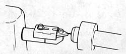
In order to cut properly, the top edge of the cutter tip must be aligned with the drive and cup centers.
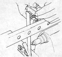
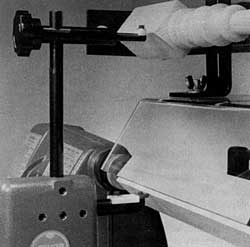
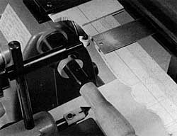
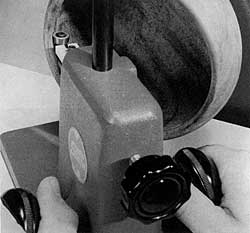
Begin by placing the tool rest assembly on the table with the cutter tip facing the drive center. Adjust the table height until the top edge of the cutter is aligned with the tip of the drive center as shown in Figure 13-3. Lock the table height.
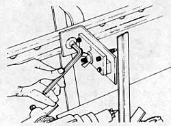
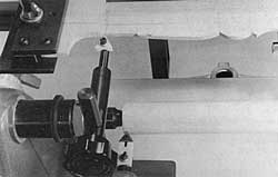
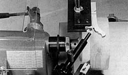
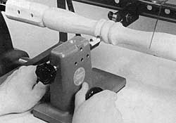
Then move to the opposite end of the lathe and check the alignment of the top edge of the cutter with the cup center (Figure 13-4). Raise or lower the tailstock as needed and lock it in place.
Note: Although raising or lowering the tailstock will alter the normal center-to-center alignment of the lathe, overall performance of the duplicator will not be affected. Correct cutter height is extremely important when using the lathe duplicator. If you plan to switch back and forth to conventional lathe turning, you may want to put a pencil mark on the tailstock mounting tubes, so you can easily return to the normal alignment position.
Template Center Alignment
For accurate duplication, the template centers must be aligned with the drive and cup centers.
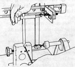
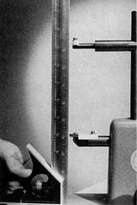
First, loosen the left hand template bracket mounting screw and slide the template bracket in the channel until the tip of the template center is even with the tip of the drive center, then tighten the template bracket mounting screw (Figure 13-5).
Next loosen the two cap screws, so that the template center can be positioned directly over the drive center. Check this alignment with a square placed both in front of and behind the centers. When the alignment is correct, tighten the two cap screws (Figure 13-6).
Repeat this procedure to align the cup center with the other template center.
Follower to Cutter Alignment
For accurate duplication, the follower tip must be directly above the cutter tip.
Begin by adjusting the height of the follower tip until it is even with the template center. Wiggle the follower support rod as you tighten the knob to be sure the screw is seated on the flat of the upright support rod.
Then loosen the setscrew for the follower upright. Align the cutter tip with the cup center and the follower tip with the template center. Tighten the setscrew on the upright (Figure 13-7).
Cutters
A total of five different cutters are available for the lathe duplicator and each cutter is supplied with a matching nylon follower tip which traces the profile of the template or pattern during duplication.
All of the cutters except the cone cutter are made of carbide and will stay sharp for many hours of turning. Warning: Never attempt to grind these carbide cutters because the dust can produce eye and skin irritation as well as respiratory system and internal organ damage.
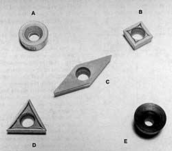
The cutters are shown in Figure 13-8 and are described below:
1/2″ Round Cutter-This is the best cutter for initial shaping. It is also very good for forming graceful curves, cove cuts and dishing.
3/8″ Square Cutter-The square cutter may be used for rough shaping, but it is best for turning square corners, grooves, short dowels, plugs and straight profiles. It is a good choice for forming tenons when making multi-section turnings.
35° Diamond Cutter-Best for turning fine beads, deep grooves, sharp corners and intricate detail because the narrow tip allows greater penetration.
60° Triangle Cutter-This is often considered the universal cutter because of its versatility. It produces good results in work ranging from rough shaping down to medium detail.
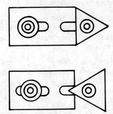
Normally the triangle cutter is mounted with the point facing the workpiece, however, it may also be used with a flat side facing the work if a square cutter is not available (Figure 13-9).
1/2″ Cone Cutter-The cone cutter is recommended for spindle turning only. It cuts quickly for rough shaping and is ideal for fin-ishing cuts when the shape of the turning permits.
The four carbide cutters cut with a scraping action and produce a somewhat rough surface. The cone cutter, however, is made of steel and has a sharpened edge which shaves the wood instead of scraping it away. This allows the cone cutter to cut faster and more smoothly, but the cutting edge will not last as long as the carbide cutters. Warning: The cone cutter is not recommended for faceplate work because its sharp cutting edge tends to bite too deeply into the end grain of the workpiece.
To get the longest life from the cone cutter, divide the tip into quarters and use one section of the cutting edge until it is dull. Then mark that section with a colored marker and rotate the tip 90° to the next section. Sharpen or replace the cone cutter when the entire edge becomes dull.
Turning Characteristics of Common Woods
Because most lathe duplicator cutters cut with a scraping action, the density and grain structure of the wood will affect the quality of the turned surface and the amount of sanding required. Generally speaking, the best results will be achieved with very hard woods which have straight, even, closed grains. Softer woods or those with pronounced annual rings often chip, tear and feather and will re-quire considerably more sanding.
Refer to Table 13-1 to find the turning characteristics of various common woods
| Tabel 13-1: Turning Characteristics of Common Woods | ||
| Wood | Characteristics | Suitability |
| Beech, birch, cherry, hard maple, rosewood, ebony, Honduran mahogany | Very hard, consistent woods with tight, closed grain pattern. | Excellent |
| Walnut, soft maple, Philippine mahagony, teak, and many fruitewoods | Slightly softer woods or those with more open grain structure. | Good |
| Red oak, hickory, ash, sassafras, red cedar, white pine, sugar pine | Softer woods or those with open or stringy grain structure. | Fair |
| Basswood, balsa, cypress, redwood, yellow pine, western cedar | Very soft woods with open, stringy or irregular grain. | Poor |
Safety
Warning: Before using the lathe duplicator, read and understand these important safety instructions:
- Wear proper eye and ear protection.
- Keep your hands, fingers and other parts of your body at least 2″ away from the rotating workpiece until it is rounded. After It is rounded, use caution when you get close to the rotating workpiece. Do not touch the workpiece as it turns.
- Keep the guard In place whenever you are performing turning operations. Position it not more than 1/2″ from the workpiece.
- When turning glued-up stock, make sure the glue joints are strong. Glue the stock and leave it clamped for at least 24 hours prior to turning.
- Wear proper apparel. Never wear jewelry, gloves, ties, loose clothing or clothing with long sleeves. Keep long hair tucked under a hat. Jewelry, gloves, ties, clothing and hair could become entangled in the workpiece.
- When mounting stock between the centers, the spurs of the drive center and the cup of the tailstock center must penetrate at least 1/16″ into the stock. Do not use a drive center or tailstock center if the point is damaged. The stock could be thrown from the lathe.
- Wax or soap the end of the stock that mounts to the cup center. This lubrication helps keep the center from wearing into the stock and causing the stock to loosen on the lathe. The ball bearing live center is highly recommended for use with the lathe duplicator.
- When mounting stock to a faceplate, use #12 x 1-1/4″ long screws. The screws must penetrate at least 1″ into the stock. The surface of the stock that’s against the faceplate must be smooth and true.
- Cut faceplate stock round and spindle stock that’s more than 3″ square into an octagon. This removes excess stock, minimizes imbalance, reduces vibration and makes turning large diameter stock safer and easier.
- Check the balance of the workpiece. Prior to mounting workpieces more than 3″ in diameter, check and adjust the center of balance (dynamic center). Unbalanced workpieces could be thrown from the lathe.
- Do not turn on the power with the cutter or any part of the tool rest assembly against the workpiece. Turn on the machine and let it come up to speed before starting the cut.
- Do not stand In the line of rotation of the workpiece when you first turn on the machine. If the machine is set on the wrong speed or the workpiece is unbalanced or improperly mounted, the workpiece could be thrown from the lathe.
- Feed the cutter slowly into the workpiece. Use both hands to hold onto and control the tool rest assembly.
- Periodically, turn off the machine and check that the workpiece is held securely between the centers or on the faceplate.
- Do not lean across or reach underneath the lathe while it is running.
- Do not try to stop the lathe by grabbing the stock or any part of the machine. Do not part the stock completely or turn the spindle down to such a small diameter that it snaps on the lathe. This can be extremely dangerous.
- Do not turn stock with splits, loose knots, or other defects that could cause the stock to break, splinter or come loose while turning. Never turn second-hand lumber. If you hit a nail or screw, you could be hit by pieces of metal.
- Remove the lathe duplicator components from the Mark V before sanding or finishing a workpiece on the lathe.
- Do not grind the carbide cutters. The dust created by grinding the carbide can cause eye and skin irritation as well as respiratory system and internal organ damage.
- Do not allow the cutter to come in contact with the parts of the lathe duplicator or Mark V. The cutter will cause damage to the parts and you could be hit by pieces of metal.
Speeds
Warning: As with all Mark V accessories, selecting the proper speed dial setting is important to help prevent damage to the equipment or injury to the operator. Generally, when using the lathe duplicator, slower speeds are used for large stock or during initial rounding operations and then the speed is increased for final shaping and sanding.
Refer to Table 13-2 to determine the correct speed for each operation.
| Table 13-2: Lathe Duplicator Speed Chart | |||
| Size of Stock | Rounding | Shaping | Sanding |
| Up to 2″ dia. | C (950 RPM) | F (1300 RPM) | K (2050 RPM) |
| 2″ to 4″ dia. | B (850 RPM) | E (1150 RPM) | J (1900 RPM) |
| 4″ to 6″ dia. | A (750 RPM) | D (1050 RPM) | H (1600 RPM) |
| Over 6″ dia. | SLOW (700 RPM) | A (750 RPM) | B (850 RPM) |
| Note: These speeds are for 60 hz. operations. |
Patterns and Templates
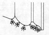
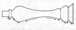
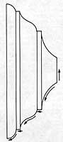
The template support assemblies of the lathe duplicator are designed to hold either flat templates or three dimensional patterns. Flat templates are used for duplicating either spindles (Figure 13-10) or faceplate turnings. Three dimensional patterns are generally used only for duplicating spindles (Figure 13-11). Although it is sometimes possible to use an existing turning as a pattern for faceplate work, the original must usually be destroyed in order to mount a cross-section of it above the workpiece.
A three dimensional pattern can be an original turning-such as a table leg which you have just created by freehand turning-or it could be a spindle from an antique chair you are trying to repair or reproduce. It could even be a broken piece which has been glued back together to serve as a pattern. Appearance isn’t important, but shape is, because every defect in the profile of the pattern will be duplicated in the workpiece.
Template Basics
There are four lines on all templates which are absolutely essential. They are:
- Centerline which is used to locate the template in the template clamps directly over the center of the workpiece. This is the most important line on the template.
- End lines show the end of the final piece and allow you to make certain enough stock is available at each end to complete the turning.
- Profile line which guides the follower tip while the cutter tip duplicates the shape in the workpiece.
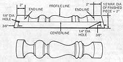
To prevent interference, spindle templates should have 2″ of extra stock at each end (Figure 13-12). They may, however, be secured with only one setscrew in each clamp. Faceplate templates must be at least 3-1/2″ wide, so that both setscrews will engage the template (Figure 13-13).
For some faceplate turnings- such as a thin-walled bowl-one template may not be practical because it would be too fragile. In these cases, you will need separate templates for the inside and outside profiles-or you can make one template with two centerlines (Figure 13-14) and reposition it after turning the outer profile. In either case, accurate construction is extremely important.
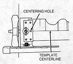
After a template has been mounted and you are sure its position is correct, you can drill a 1/4″ locating hole through the template clamp (Figure 13-15). The template can then be removed and replaced very accurately by inserting a 1/4″ dowel through the centering hole in the template clamp and template.
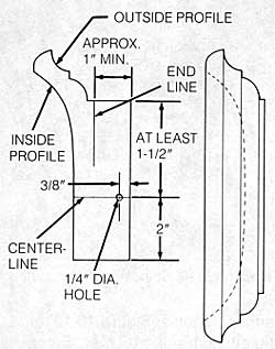
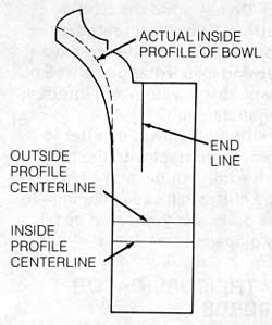
Figure 13-14. A template with two centerlines for making a thin-walled bowl.
Template Materials
Templates may be made from a variety of materials. Probably the most popular and economical choice is 1/4″ thick tempered hardboard. It is hard and durable and yet it is easy to cut and sand.
For greater accuracy and durability, use sheet acrylic materials. Although somewhat more difficult to cut and sand, acrylic templates will last almost indefinitely. After an acrylic template has been cut and shaped, scribe the critical lines into its surface. Then remove the paper covering. The clear template allows light to shine through the template and eliminates shadows on the workpiece. For better visibility, you can also accent the profile edge of the template with a colored marker.
Templates may also be made of wood if thin stock or a thickness planer is available. Hard, closed grain woods are best. Softer, more open grained woods are not recommended because the template is easily dented or chipped and becomes useless.
Template Construction
Templates are made by creating a full size drawing of the turning, attaching the drawing to suitable stock with rubber cement and then cutting out the profile with a band saw, jigsaw or scroll saw.
If your project plans are not full size, they must be enlarged. This may be done by using a grid system to scale up the drawing or by using a panto graph to trace and enlarge the image. Even more accurate enlargements can be made with a copier machine. When you have your full size drawing, check to be sure the available cutters will fit into any narrow grooves or profiles.
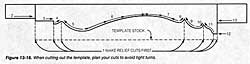
Once the full size drawing has been attached to the template stock, cut out the template (Figure 13-16). Note that the first cuts to be made are relief cuts that let waste stock fall away as you cut the profile. This helps keep the blade from binding in tight spots and lets you make each cut more precisely.
Next cut each section of the profile staying slightly outside the line to leave a little stock for final sanding. Use multiple cuts whenever necessary to avoid difficult turns with the blade. The profiles will be smoother with less sanding required.
Finally, sand to the profile lines until the template is perfectly smooth. This can be done with sandpaper, triangle and half round files, or even an emery board. Remember that any bump or chip in the profile edge will be duplicated in your final turning.
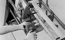
Spindle Turning
Spindle turning includes any turning where the workpiece is held between the drive center and tail-stock center. Warning: When mounting spindles, it is important for the drive center and tailstock center to be driven at least 1/16″ into the ends of the stock. Although the tailstock live center is recommended for use with the lathe duplicator, the standard cup center should be used for scoring the end of the stock. Caution: Driving the live center into the stock with a mallet will damage the bailbearings in the live center.
Mount the template or pattern above the work piece as shown in your Lathe Duplicator Owners Manual. If you are using a flat template, the center If you are using a three dimensional pattern, rotate the template brackets and seat the tips of the template centers securely into the ends of the pattern (Figure 13-18), so it cannot turn during duplication. If your pattern includes a square section such as the top of a table leg, the square corner must face the follower tip, not the flat side (Figure 13-19).line should be visible through the centering holes (Figure 13-17) and the end of the template should fit securely inside the template clamps.
Make sure the end lines of the template or pattern are inside the ends of the workpiece (Figure 13-20). Adjust the location of the template brackets if necessary.
Finally adjust the guard. It should be within 1/2″ of the stock and just high enough for the cutter to reach the workpiece.
Rounding
Turn on the Mark V and set the speed dial to the proper speed. Grasp the handles of the tool rest assembly and advance the cutter into the stock until it begins to cut. You can be aggressive, but do not force the cutter in so hard that it stops the workpiece.
Round off the corners, working in small sections from one end of the stock toward the other until it is completely rounded. If you are working on a long workpiece, round one area then turn off the Mark V and reposition the table and guard. Warning: Check to be sure the stock is still securely mounted. Then continue rounding.
Rough Shaping
During rough shaping you should leave about 1/32″ of stock for removal during final detailing. This may be done by keeping the follower tip away from the template, but if you are new to the duplicator you may want to retract the cutter to avoid mistakes (Figure 13-21).
To retract the cutter, loosen the three setscrews that hold the cutter support and turn the cutter adjusting knob one-half turn counterclockwise. Press the cutter support back against the adjusting stud and tighten the front and rear setscrews only. The center setscrew cannot seat in the positioning groove when the cutter support is retracted.
To begin shaping, move the table and guard to either end of the work piece. Turn on the Mark V and set the speed dial to the proper speed.
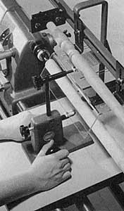
Start by shaping the larger diameters and then progress to the smaller ones. Don’t force the cutter into the stock or press so hard that you deflect the turning. Use a steady rest (Figure 13-1) to support long or thin turnings.
Use a back and forth motion, working down into each contour. Also keep the follower perpendicular to the profile of the template (Figure 13-22), so extra stock will be left on all surfaces.
When you are cutting properly, you will produce large chips, not fine dust or a burnished surface. If cutting is slow, check the table height adjustment to be sure the cutting edge is even with or slightly below the center line of the turning or lathe centers.
Final Detailing
If you have retracted the cutter for rough shaping, it should be readjusted before making your final passes. Be sure that the center setscrew is seated in the positioning groove of the cutter support, so that the cutter is exactly even with the follower. Align the cutter sup-port as described earlier and tighten all three setscrews.
Final detailing requires a certain “art”, but the duplicator makes it easy to learn. Use a light touch and move the cutter in an “uphill” direction when shaping beads and coves (Figure 13-23). The smoothest surface is usually produced by dragging the cutter sideways-not by approaching the workpiece with the point of the cutter.
Also be careful not to press so hard that you deflect the template or rock the base of the tool rest assembly. If you do happen to make a mistake, don’t panic. It is often possible to save the turning by removing the follower and smoothing out the mistake by turning freehand. Although the piece will not be an exact duplicate, slight variations may not be noticeable in the final project.
Turning to Exact Diameters
You can turn duplicate pieces even if a template or pattern is mounted slightly out of alignment, but some projects require turning to an exact diameter. Creating a tenon for joining a spindle and faceplate or sections of a long bedpost are two examples.
To verify the alignment, turn a flat area at the desired location, but leave enough stock so that the follower tip does not contact the template. (The cutter must be in its normal position-not retracted.)
Use a good set of calipers to accurately measure the turned diameter. Then measure from the follower tip to the centerline of the template (Figure 13-24). If the alignment is correct, this distance will be exactly one half the diameter of the turning. If not, make any necessary adjustments before proceeding. For very critical work it is a good idea to make a practice turning from scrap stock to verity the setup before turning the actual project pieces. Note: The tailstock chuck arbor is useful for drilling mating holes for joining two or more turnings.
Parting Cuts
After all turning and sanding on the lathe has been completed, remove the turning from the lathe and use a bandsaw or coping saw to trim off the scrap at the end of the workpiece. Warning: Do not part the stock completely on the lathe.
If you wish to cut a square shoulder where the stock will be parted, use the square cutter or reverse the mounting of the triangle cutter and use its side.
Faceplate Turning
Faceplate turnings are made with the stock mounted to a faceplate which is attached to the Mark V main spindle. Follow the instructions in Chapter 12 when mounting faceplate turnings.
Warning: Make sure the workpiece does not have loose knots, splits or defects. Use #12 x 1-1/4″ or larger screws to attach the stock to the faceplate. Allow glue joints to dry for at least 24 hours and cut the stock round on the bandsaw before turning.
Setup
All face plate turning should be done at the far right end of the Mark V. Remove the right-hand template support. Move the table as far to the right as it will go and reposition the power plant and left-hand template assembly.
Mount the template in the template assembly with the edge of the template firmly seated against the spacer in the clamp. Then tighten the two setscrews to hold the template securely. Accurate alignment of the template is extremely important to assure accurate diameters and eliminate unplanned tapers in the final turning.
Loosen the template bracket screw and position the template over the workpiece. Use the tool rest assembly as an alignment gauge to be sure the end line on the template is inside the left edge of the workpiece (Figure 13-25). Tighten the template bracket screw.
Finally, mount and adjust the guard (Figure 13-26). Warning: The brackets should be attached to the left and center slots of the guard and the guard should extend from the power plant over the workpiece. Adjust the guard so it is as close to the workpiece as possible and just high enough for the cutter to pass freely underneath it.
Rough Shaping
The techniques for rough shaping faceplate workpieces are very much like those for spindles. Work in small areas, beginning with the larger diameters. The cutter may be retracted to leave some stock for final detailing.
If you are cutting properly, you will see large chips. As the profile takes shape, these chips will become curled shavings often several inches long.
Generally you should rough shape the outside profile and then begin roughing the inside contour. The exception is when you are working on a project-such as a thin walled bowl-where two templates or two centerlines are required for the outside and inside profiles.
In these cases, it is usually easier to continue with final detailing of the outside profile before beginning on the inside. This will eliminate having to reposition the templates for final shaping. If repositioning will be necessary, drill the 1/4″ alignment hole (Figure 13-15) before removing the template and be sure the setscrews return to exactly the same in-dentions in the template.
Final Detailing
Reposition the cutter if it has been retracted and begin cutting with a light touch. Work “uphill” on beads and coves, but “downhill” when shaping from the top of a sharp shoulder into a round profile (Figure 13-27).
Undercutting
Undercutting involves cutting an inside diameter that is larger than the opening. This is quite common in salad bowls and similar projects where the middle is wider than the top or bottom.
The free-floating tool rest lets you make undercuts with only minor limitations (Figure 13-28). First is the limit of the cutting angle you can achieve before the tool rest base runs into the turning. Second is the depth of the undercut before the lip of the turning begins to rub on the underside of the cutter support. These limitations are reduced as the size of the turning increases. In some cases, you can increase the undercut by extending the cutter support up to one inch and making light passes freehand.
Production Tips
If you are making a number of spindle and faceplate turnings, these tips will help speed up the job and eliminate needless work.
- Complete each operation on all pieces before moving to the next. For example, prepare all the stock, make all the turnings, plus sand and finish all the parts.
- Mounting three or four turn-ings on extra faceplates will be faster than removing and remounting each piece.
- When using different cutters for rough turning and final detailing, rough shape all turnings before changing tips or getting an extra tool rest assembly.
- Drill centering holes in templates to speed up remounting and realignment.
Freehand Turning
Freehand turning is very much like duplicating except no template or pattern is required. You can shape the piece any way you imagine it (Figure 13-29). The setup is the same except that the template brackets, the follower and the follower upright support are removed. Leave the channel assembly and guard in place.
Sanding and Finishing
Sanding and finishing a turning are much easier done on the lathe than removing it and finishing it by hand. Warning: Before you start, remove all lathe duplicator components. Caution: Lay a cloth over the way tubes to catch grit and finish.
For sanding, use quarter sheets of sandpaper folded into thirds. This gives you a rigid piece, yet it will bend to fit the shape of the turning and the thickness helps protect your fingers from heat build-up (Figure 13-30). Warning: Never wrap sandpaper, steel wool or a rag around the turning and never use a rag with frayed edges. They could easily pull your fingers into the workpiece.
Turn the Mark V on and set the speed dial to the correct speed. Begin working with new 100-grit paper and light pressure. Then switch to used 100-grit paper. Finish sanding with new and used 150-grit paper. For open grain woods, wet the surface to raise the grain between sandpaper changes. Allow the water to dry before sanding.
For a smoother surface and reduced sanding time, dismount the spindle, turn it end-for-end and sand in the opposite direction. Warning: When remounting the stock, be sure to put enough pressure on the quill to engage both the drive and cup centers. You can reverse the rotation of a faceplate turning by mounting the faceplate on the upper auxiliary spindle.
For finishing, use avery low speed and prepare a natural oil finish with the stain mixed in. Polyurethane is not recommended because it will dry too quickly. Mask any areas to be glued later.
Soak a rag and a piece of fine, slightly used wet/dry sandpaper in the finish. Use the rag to apply the finish to the turning. Then sand. Repeat, adding more finish until a mixture of finish and sanding dust covers the entire turning. Rub this paste with your hands and let it set for a minute or two or until it becomes sticky. Then buff the turning and let it dry. Apply additional coats of finish, but do not sand.