Lathe turning is perhaps the only woodworking operation in which, after stock is cut to size, you can start and finish a project in just one mode of the Mark V. But it also demands a good deal more skill and patience than other operations. If you’re just beginning, don’t be discouraged. Turning takes a little practice, but once you get the hang of it, it’s one of the most satisfying woodworking techniques.
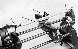
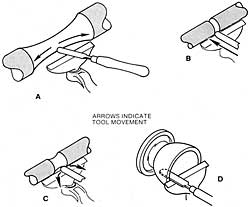
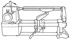
Figure 12-1. The accessories that are used for spindle turning operations are the: (A) drive center, (B) tool rest, (C) cup center, (0) tailstock, and (E) optional steady rest. The steady rest helps to reduce whip and vibration
The lathe hasn’t changed in principle since it was a primitive, bow-powered tool that is said to have been invented in ancient Egypt. It remains a means of turning stock at controlled speeds so sharp tools may be pressed against it, shaping it symmetrically. Electric motors have replaced the various hand powered or foot powered devices originally used, but the quality of the output still depends on the operator’s skill in manipulating the chisels used to form the stock.
There are two basic kinds of lathe turning: spindle turning and faceplate turning.
Spindle turning is turning stock between two centers–the drive center and the cup center (Figure 12-1). Usually the end product is a long cylinder, like a table leg or a candle stand.
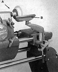
Faceplate turning is turning with the stock mounted to a faceplate (Figure 12-2). This faceplate is, in turn, mounted to the main spindle. The end product is usually shorter and wider than spindle turning, like a platter or bowl. Shopsmith offers two faceplates, 3-3/4″ and 6″ in diameter.
Setup and Features
To set up your Mark V in the lathe mode, follow the instructions in the Owners Manual that came with your machine.
As you work in the lathe mode, you’ll find that the Mark V is an extremely capable lathe with several special features.
- It has swing of 8-1/8″, so that you can turn stock up to 16-1/4″ in diameter. It will hold a spindle up to 34″ long between the center-long enough to turn table legs.
- The quill feed holds the spindle in place between the centers.
- The tool rest is 8″ long and swivels a full 360 degrees. It adjusts up or down with the table height mechanism and sideways by sliding the carriage along the way tubes. The Model 510 tool rest arm has a center post position that is used when turning heavy stock.
- The speed dial provides a broad range of speeds for a variety of lathe operations from rough shaping to finish sanding.
- The tailstock has an eccentric mount to aid in turning tapers.
- A lathe steady rest is available that helps to reduce whip and vibration of the spindle stock.
Lathe Tools
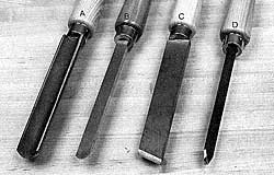
There are four basic tools that you need when doing lathe work (Figure 12-3).
- Gouges are used to round the stock and to make concave curves called “coves,” mostly in spindle turning.
- Roundnose chisels are also used to make coves, mostly in faceplate turning.
- Skew chisels are used to make convex curves called “beads.” They can also be used to cut straight or tapered cylinders.
- Parting tools are used mostly for sizing and parting operations.
A basic lathe tool set includes 1″ and 1/2″ gouges, a 1/2″ round-nose chisel, a 1″ skew chisel, and a 1/8″ parting tool. These five tools can be used for all types of turning.
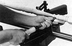
Holding Lathe Tools
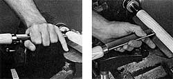
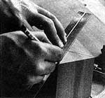
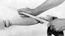
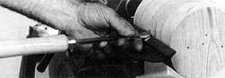
Two ways to grip lathe tools properly (reverse if left handed) are demonstrated in Figure 12-4. The left hand is usually placed on top of the blade, with the little finger toward the stock. The butt of the hand or little finger rides against the finger ledge. The right hand holds the handle of the tool and provides the movement which determines the cut. The part of the hand that rests on the finger ledge also acts as a gauge.
An alternate method of holding the lathe tools consists of placing the left hand on the blade with the thumb on top. The back of the hand rests on the finger ledge and the fingers are placed comfortably around the tool or on the finger ledge. The right hand serves the same purpose in this holding method as it does in the method mentioned previously.
When making smoothing cuts or when roughing stock to size, the tool may be moved along the tool rest parallel to the work, taking a bite that remains constant because the left hand butts against the tool rest ledge and acts as a control.
The feed of the chisel, which determines the amount of wood removed, should be slow and steady–never forced, never jabbed into the work. After the tool is in position, start the cut by advancing the tool slowly until it touches the wood.
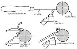
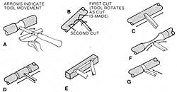
Three Cutting Actions
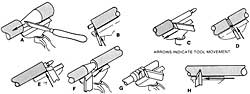
Each of the lathe chisels act in the three ways shown in Figure 12-5, depending on how you hold them.
Scraping–Scraping is the easiest and safest of the three actions and the best for the beginner to use. Many experienced operators use this action almost exclusively because it gives good results.
A scraping action with a round-nose chisel is shown in Figure 12-6. Notice that the hand position hasn’t changed except for the fingers. Placed as shown, the thumb and forefingers do most of the gripping and help to bring the cutting edge of the chisel close to a horizontal plane. This position is maintained while the chisel is advanced to the depth of the cut and then moved slowly from side to side to increase the cut’s width if necessary. Full depth does not have to be reached at once. The chisel may be moved forward a slight amount and then moved from side to side as the pivot point is maintained. The procedure is repeated until the full shape is formed. Each “pass” removes a little more wood.
Cutting–This action calls for bringing the tool edge into the surface almost as if it were a knife.
The feed should be slow and the cut should be light. Warning: If you jab the chisel into the work-piece suddenly or deeply, the chisel will be wrenched from your hands. You could be seriously injured. At the very least you will ruin the workpiece by cutting and lifting a large splinter from it. Don’t use the cutting action until you have practiced enough with the scraping action to be thoroughly familiar with each tool and what it can do. Once you have become proficient with the cutting action, you’ll find that it leaves a surface smooth enough to finish with a little touch-up.
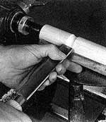
Shearing–The shearing action is usually limited to the skew and gouge. It is a cutting action with the tool edge moved parallel to the work, taking a constant bite, shearing away a layer of wood from the surface of the stock. A shearing action with the gouge is illustrated in Figure 12-7. The shearing action of cutting beads with a skew is shown in Figure 12-8. Shearing a cove is one of the easier cuts. Since the tool is held on edge, move your thumb behind it to steady it while making the cut. When the gouge is sharp and properly held, wood is removed rapidly and the surface is left smooth.
While each of the tools does certain operations better, the overlap is so great that no hard-and-fast limitations can be set down for each one. Each tool will cut differently, depending on the action, the angle, and the way it is moved. Practice with each tool until you have the feel of each of them. When you arrive at this point, habit will take over and your use of the tools will become an individual application that is standard with you.
Using the Gouge
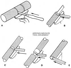
The gouge, one of the more versatile turning tools, can be used with any of the three cutting actions. At times it is applied so all three cutting actions come into play (Figure 12-9).
It is the only tool to use when doing initial rounding (Figure 12-10). This is essentially a shearing cut with the gouge held on its side and moved parallel to the work. Depth of cut is maintained by a finger resting against the tool rest ledge.
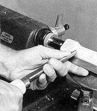
Rounding should be started somewhere along the length of the stock with the gouge moved in the direction indicated by the arrows in Figure 12-9E. You’ll find it is easier to work from a midpoint toward each end of the stock instead of making one continuous cut from end to end.
To make rounding cuts in a limited area, use the gouge between sizing cuts made with the parting tool or marks penciled on the workpiece.
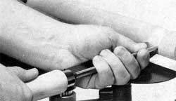
Figure 12-11. The gouge, when used with a scraping action, will form a cove that duplicates the size and shape of the gouge’s cutting edge.
Figure 12-11 shows how you can use the gouge in a scraping action to form a cove whose size and shape is dictated by the tool. The gouge is held in a horizontal position and slowly moved directly forward. Warning: Do not remove too much material at once. Retracting the gouge frequently will allow waste material to fall away.
The shearing action is a more advanced way to form a cove with the gouge. Begin with the gouge on its side as if you were preparing for a rounding cut. Feed the gouge forward to contact the stock; then rotate it on the tool rest as you move it toward the center of the cove (Figure 12-12). Work this way from both sides of the cove toward its center. As the gouge is manipulated, the action changes from shearing to scraping (Figure 12-13), which occurs at the full depth-of-cut point only.
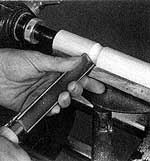
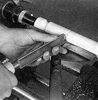
Using The Skew Chisel
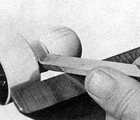
Typical applications of the skew chisel are shown in Figure 12-14. While professionals use the skew mostly in a shearing action, it can function efficiently while cutting or scraping. A common scraping action is shown in Figure 12-14E with the chisel held to square off the end of a cylinder. When held this way, the chisel’s sharp point removes material quickly and leaves a reasonably smooth surface. The same result is obtained by using the point of the skew in a cutting action (Figure 12-14B). When used this way, the skew works like a knife, severing wood fibers and leaving a surface that requires little sanding.
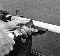
Tapers are formed by starting the cut with the heel of the blade and raising the handle as you slide the chisel along the tool rest. To smooth a taper that was formed with another tool, use the skew as shown in Figure 12-14A or F. This can be a scraping or a shearing action. If you move the skew so only its heel contacts the work-piece, it will shear. If you position the skew so its edge is parallel to the workpiece and then advance it while maintaining tool-to-work-piece contact, the action will be scraping.
Probably the smoothest surfacing cut of all is shown in Figure 12-14H where a shearing cut is being used to smooth a cylinder. The cutting edge of the skew is held at an angle to the longitudinal axis of the workpiece. When done correctly, the surface of the work-piece is smooth with a finish that looks burnished. It will take practice.
The skew is used to form beads. Like a cove, the bead requires three marked or imagined dimension lines: one to indicate the bead’s center and one on each side of the center to indicate total bead width.
Start by placing the heel of the skew lightly on the bead’s center-line so its edge is tangent to the curve you want to form. Move the skew into the workpiece. At the same time, rotate and lift the handle to follow the curve of the bead. It will take several passes to form one-half of the bead (Figure 12-15). Follow the same procedure, but work in the opposite direction, to form the other half of the bead (Figure 12-16).
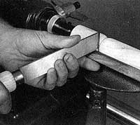
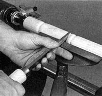
Figure 12-16. Finish the bead by repeating the procedure, this time working in the opposite direction. It takes practice to do this kind of shaping efficiently.
Using the Roundnose Chisel
The roundnose chisel is always used in a scraping action (Figure 12-17) and is the only tool to use for hollowing. In the latter application, the tool rest must be positioned to provide maximum support for the chisel even if it has to be placed inside the hollow that is being formed.
Using the Parting Tool
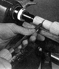
The parting tool is most often used in a scraping action with the edge of the blade resting on the edge of the tool rest and with blade feed directly forward, whether the cut is square or at an angle to the work-piece (Figure 12-18).
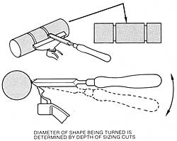
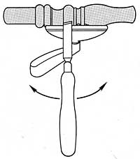
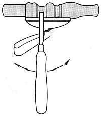
The parting tool is often used to determine the depth of cut or the diameter of the final shape. To speed up the procedure when making preliminary sizing cuts, handle the tool as shown in Figure 12-19. Start with the tool horizontal, then slowly raise and lower its cutting edge as the cut deepens.
Planning the Design
Before you attempt to form a turn-ing, you must first plan the design. Otherwise you may end up with an unattractive project.
The best way to plan the design is to draw a full-size plan with the shapes and dimensions marked, so that before you start you will know exactly what shapes you are going to cut and where.
Here’s an example of how to plan the design for a spindle turning 12″ long and 3″ in diameter: Draw a rectangle 12″ by 3″ on a piece of paper. Draw a center line down its length. Break up the length into design areas by draw-ing horizontal lines that are proportional and pleasing. Let the base design occupy the bottom 3″; use 7″ for the transition from base to top and leave the remaining 2″ for the top.
Lathe Safety
Warning: Before using the lathe, read and understand these important safety instructions:
Danger Zone–The danger zone on the Mark V in the lathe mode changes as the turning progresses. Before the stock has been rounded, the danger zone extends 3″ out from the stock in all directions. After the stock is rounded and while it’s being shaped, the danger zone extends 1″ out. After the stock is completely shaped and the tool rest has been removed, you can safely put your hands near enough to the workpiece to sand it on the lathe.
Always keep your fingers and hands out of the danger zone. When you work at the lathe, be careful not to touch the stock as it turns, until you have finished shaping it. In particular, be careful not to let your fingers or hands slip between the workpiece and the tool rest. Keep both hands on the tool you’re using and in front of the tool rest.
Before sanding your workpiece on the lathe, turn off the machine, let it come to a complete stop, and remove the tool rest.
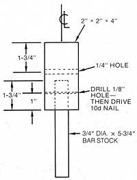
Balance–This is extremely important when turning glued-up stock, long stock and stock more than 3″ in diameter. Check the balance of your spindle and face plate stock after you’ve marked the centers. To do this, drive a standard 8 penny nail straight into each center.
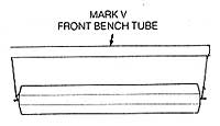
Use suitable string to hang the stock in a level position from the front bench tube of the Mark V or a saw horse. The ends of the string should be looped around the nails (Figure 12-20). Gravity will pull the heavy side down. Use a jointer, bandsaw or hand plane to remove no more than 1/32″ at a time from the heavy side until the stock re-mains stationary when rotated to three positions 90 degrees apart.
- Wear proper eye protection and a dust mask.
- When turning glued up stock, make sure glue joints are strong. Glue the stock and leave it clamped for at least 24 hours prior to turning.
- Do not wear jewelry, gloves, ties, loose clothing or clothing with long sleeves. Keep long hair tucked under a hat. Jewelry, gloves, ties, clothing and hair could become entangled in the stock.
- Do not turn stock with splits, loose knots, or other defects that could cause the stock to break, splinter or come loose while turning.
- Cut stock that’s larger than 3″ x 3″ into an octagon. This removes excess stock and makes turning safer and easier.
- When mounting stock between the centers, the spurs of the drive center and the cup of the cup center must penetrate at least 1/16″ into the stock. Do not use a center if the point is damaged. The stock could be thrown from the lathe.
- Wax or soap the end of the stock that mounts to the cup center. This lubrication helps keep the cup center from wearing into the stock and causing the stock to loosen on the lathe.
- When mounting stock to a faceplate, use #12 x 1-1/4″ long screws. The screws must pene-trate at least 3/4″ into the stock. If the screws are being driven into the end grain, the screws must penetrate at least 2″ into the stock. Use #12 x 2-1/2″ long wood screws. Before mounting stock to a faceplate, to minimize imbalance cut the stock round.
- Position the tool rest no more than 1/4″ from the stock. Maintain this distance while turning. Before turning on the machine, rotate the stock by hand to make sure it clears the tool rest. Never turn without the tool rest. Rest the tool on the tool rest before cutting, shearing, or scraping.
- During turning, periodically turn off the machine and check to make sure the stock remains securely mounted.
- Do not lean across or reach underneath the lathe while it is running. Do not touch the rotating stock while the tool rest is mounted. Round all stock at “Slow” speed.
- Large heavy stock will fly off the lathe if you try to round at too high a speed. Feed the tool very slowly into the stock. Never force the tool or remove too much material in one pass. Hold the tool firmly in both hands and against the tool rest.
- Never try to stop the lathe by grabbing the stock or any part of the machine.
- Do not part the stock completely or turn the spindle down to such a small diameter that it snaps.
- Always remove the tool rest before sanding the turned stock on the lathe.
- When turning large heavy stock, use the center post position on the tool rest arm (Model 510 only).
- Always use the proper speed for the stock size and operation.
Lathe Speeds
Before you mount stock on the lathe be sure the speed is set at “Slow.” After the stock is mounted, turn on the machine, set the speed dial to the proper speed and let the lathe come up to speed.
The operating speeds for lathe turning are determined by the size of the stock you’re turning and the operation you’re performing-whether you’re rounding the stock, shaping it, or finish sanding. Generally, you can use slightly faster speeds as you progress from rounding to shaping to sanding. You can also use slightly faster speeds with smaller stock. The larger the workpiece, the slower the speed should be for each operation.
To help determine the right speed for the job, use Table 12-1.
| Table 12-1: Lathe Turning Speed Chart | |||
| Size of Stock | Rounding | Shaping | Sandin |
| Up to 2″ dia. 2″ to 4″ dia. 4″ to 6″ dia. Over 6″ dia. | C (950 RPM) B (850 RPM) A (750 RPM) Slow (700 RPM) | F (1300 RPM) E (1150 RPM) D (1050 RPM) A (750 RPM) | K (2050 RPM) J (1900 RPM) H (1600 RPM) B (850 RPM) |
| NOTE: These speeds are for 60 hz. operations. |
Spindle Turning
All spindle turning projects involve these six basic steps:
1. Mounting. Mounting the stock on the lathe is an extremely important operation. Warning: Improperly mounted stock is dangerous and difficult to turn.
2. Rounding. The first step is to turn the stock down to a rough cylinder.
3. Sizing. Once the stock has been rounded, mark the positions of the shapes you want to make and turn them down to their approximate diameters.
4. Shaping. Turn the beads (convex curves) and coves (concave curves) in your design.
5. Sanding. After the stock is shaped, remove the tool rest and sand the workpiece smooth.
6. Parting. After the final sanding, reinstall the tool rest and remove the waste stock (if any) from the turning.
Mounting
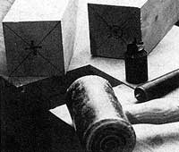
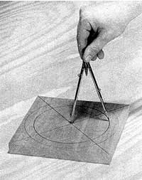
To mount stock between the lathe centers, you must first find the center of the stock. To find the center of a square workpiece, use a straightedge and draw two diagonal lines on each end of the workpiece, from corner to corner (Figure 12-21). Where these two lines intersect marks the center of the stock. To find the center of a round workpiece, use a center finder.
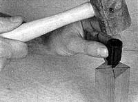
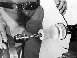
With a plastic or rawhide mallet, seat the drive center in one end of the workpiece and the cup center in the other.
Caution: Do not hit the centers with a metal hammer-you will ruin them. Position the center point at the center mark; then hit the center sharply (Figure 12-22). When properly seated, the drive center will leave four slots where the spurs bit into the wood. The cup center will leave a small circle (Figure 12-23). Warning: The spurs of the drive center and the circle of the cup center must penetrate into the wood at least 1/16″ in order to mount the stock securely on the lathe.
If you’re working with hardwood, drill 1/8″ diameter holes, 1/2″ deep in the center of both ends of the workpiece, and saw diagonal kerfs 1/8″ deep. This will help seat the drive center.
If the work piece you’re turning is more than 3″ square, cut off the square corners to form an octagon. This will make the work piece safer and easier to turn. Use a band saw or table saw to cut off the corners.
Mount the drive center on the main spindle and the cup center in the tailstock. Position the power plant so that the centers are about 1″ farther apart than the length of the workpiece, and lock the power plant in position. Warning: Be sure the speed dial is set on “Slow.”
Wax or soap the end of the stock that mounts to the cup center to help it turn smoothly. Hold the stock against the cup center; then extend the quill and mount the other end on the drive center. Press against the quill feed lever to be sure both the spurs and the cup are engaged. Do not release the tension. Then lock the quill in place (Figure 12-24).
Adjust the height of the tool rest for scraping or shearing, whichever you prefer. Then align the tool rest parallel to the stock within 1/8″ to 1/4″. Be sure the setscrews in the tool rest assembly are secured. Turn the stock by hand to be sure it clears the tool rest. Make a five-point check. All five locks–power plant, carriage, tool rest height, quill and tail stock–should be secure. The speed should be set at “Slow.” Turn on the Mark V. The stock should rotate smoothly, without excessive vibration.

Rounding
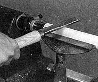
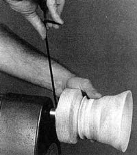
Select a gouge and lay it across the left end of the tool rest. The cup should face up and slightly toward the right end of the tool rest. The shank and handle should be pointing down and angled slightly toward the left end of the tool rest. Gently feed the cutting edge toward the stock until the tip just touches the stock. Then draw it slowly and steadily along the tool rest to the right, removing a little bit of the stock (Figure 12-25).
To reverse the cutting action, turn the gouge so the cup still faces up but slightly toward the left end of the tool rest. Feed the gouge into the stock and draw it back along the tool rest to the right. Repeat this procedure until the stock is completely round, without any flat spots.
To tell if there are any flat spots without turning off the machine, carefully let the shank of the qouge rest on the revolving stock (Figure 12-26). If the gouge vibrates or jumps up and down, the stock is not quite round. Warning: Round all stock at “Slow” speed and never remove too much stock too quickly.
Sizing
Once the stock has been rounded, “size” the stock, marking the various diameters of the beads and coves you want to cut.
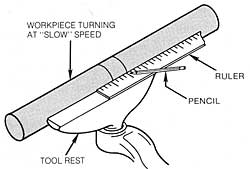
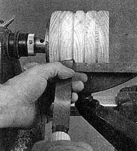
Use a pencil and a parting tool for this operation. With the pencil, scribe lines on the revolving stock to indicate where you want the beads, coves, and other parts of your spindle design to begin and end (Figure 12-27).
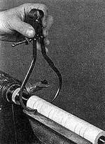
With a parting tool, cut grooves in the workpiece to indicate the position and diameter of the different shapes in your design (Figure 12-28). To gauge when you’ve reached the proper diame-ter, set a pair of “outside” calipers at the desired measurement and test the diameter where you’re cutting from time to time. When the calipers just slip over the stock at the bottom of the groove, you’ve arrived at the desired diameter (Figure 12-29).
Shaping
When you’ve marked the positions and diameters of the various parts of your design, begin to cut the shapes. Usually, it’s easiest to start with the convex curves or beads.
Select a skew chisel to round the sides of the beads. Feed the edge of the chisel slowly into the stock; then move the handle of the skew from side to side as needed to shape the bead (Figure 12-30).
After you’ve made the beads, begin to cut the coves, the concave curves in your design. Select a gouge and slowly feed it into the workpiece, gradually removing stock. As you did when you were shaping the beads, move the handle of the tool from side to side to shape the cove the way you want it (Figure 12-31).
When forming duplicate pieces, for example, chair or table legs, it’s better to work with a hardboard template (Figure 12-32). The template is a full-scale, half-profile of the part and can be used to check the turning as you go, as well as for marking initial dimension points.
Although woodworkers usually rely on skew chisels to cut beads and gouges to cut coves, you can use other tools if you wish. Select whatever seems best for you.
Sanding
It’s much easier to sand a turning on the lathe than it is to remove it and hand sand it. However, since you have to get your fingers right next to the spinning stock, you must be extremely careful.
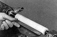
When the turning has been completely shaped, turn off the machine and let it come to a complete stop. Warning: Remove the tool rest before sanding a turning on the lathe. Turn on the machine and slightly increase the speed of rotation. Starting with medium (80#) sandpaper, begin to sand the spindle by holding the sandpaper lightly against it (Figure 12-33).
Double the sandpaper over several times for two reasons: The paper heats up quickly and extra layers of paper protect you from being burned. Also, the extra layers of paper keep your hands from contacting the rotating spindle. Work your way through progressively finer grits of sandpaper until you get the spindle as smooth as you want it. Warning: Never wrap the sandpaper entirely around the spindle or allow strands to wrap around the spindle. The spindle will grab the sandpaper or strand and draw your fingers into the rotating spindle.
Because sanding a spindle on the lathe usually requires you to sand across the grain, tiny “feathers” will develop on the surface of the spindle.
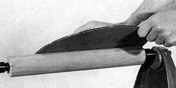
Figure 12-34. The sanding disc provides plenty of flat, abrasive surrace ror smoothing uniform or tapered cylinders.
There are two ways to remove these. The easiest is to wet the spindle with a damp rag, wait a few minutes for the water to dry and raise the wood grain, then give the spindle a final sanding with a very fine grit sandpaper. If you don’t want to wet the wood, turn the Mark V off and dismount the spindle. Remove the centers and seat them in opposite ends of the spindle. Remount the spindle, putting enough pressure on the quill to engage both the drive center and the cup center. This reverses the rotation of the spindle so that you can remove any microscopic feathers with a light sanding.
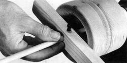
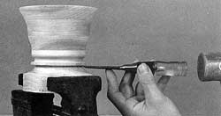
Here are several other lathe sanding tips: The Mark V sanding disc is a super tool to use when smoothing uniform cylinders or tapers (Figure 12-34). Another trick used by professionals is shown in Figure 12-35. After the work piece has been smoothed by sanding, hold a strip of wood against the work piece as it is turning. The result will be a hard, burnished surface that is fine for a natural finish but will not take a stain.
Parting
After the spindle is sanded, part the spindle from the waste stock. Using the parting tool turned on its edge, scrape away stock from either end of the spindle until the diameter is as small as it can safely go and still not break (Figure 12-36). Warning: Never part the stock completely or turn the spindle down to such a small diameter that it snaps on the lathe. Always remove the spindle from the lathe and finish cutting off the waste stock with a saw (Figure 12-37).
Faceplate Turning
Face plate turning is similar to spindle turning in some respects, but very different in others. We’ll point out those differences as we go through this basic procedure. As with spindle turning, face plate turning also involves six basic steps: Mounting, rounding, sizing, shaping, sanding and parting.
Mounting
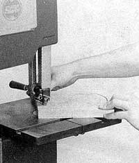
To mount stock on a faceplate, first find the center of the stock by drawing diagonal lines from corner to corner. Then scribe the outside diameter of your project (the diameter desired after rounding) on the stock. Also, scribe a circle slightly larger than the diameter of the faceplate in the center of the circle you’ve already marked (Figure 12-38). Then cut the stock round using a bandsaw or scroll saw (Figure 12-39). This removes excess stock which makes turning safer and easier.
f you don’t want screw holes in the bottom of your finished project, you can mount the turning stock to another block of wood; then mount this block to the faceplate. Select a scrap block at least 1″ thick and about the same diameter as the faceplate you’ll be using. Find the center of this scrap block; then glue the block to the turning stock, center-to-center. Put a piece of paper (brown craft paper or grocery sack) in between the block and the turning stock (Figure 12-40). Warning: Leave the pieces clamped for at least 24 hours prior to turning. Later on, this paper will make it easier for you to part the scrap block from the turning.
After the glue has set up com-pletely (at least 24 hours), mount the scrap block to the faceplate with three #12 x 1-1/4″ wood screws. Warning: Be sure the screws penetrate into the block at least 3/4″. For large, bulky faceplate turnings use longer screws and a thicker scrap block.
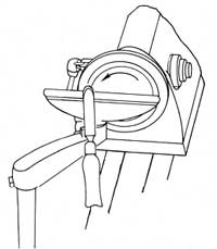
Be sure the speed dial is set on “Slow.” Then mount the faceplate on the main spindle of the Mark V (Figure 12-41). Position the tool rest to turn the outside of the workpiece first. When the tool rest is properly positioned and the set-screws secured, turn the work-piece by hand to make sure it doesn’t scrape against the tool rest. Make a four-point check. All four locks -power plant, carriage, tool rest height, quill-should be secure. The speed should be set at “Slow.” Turn on the Mark V and slowly turn the speed dial to the recommended speed for the operation. The stock should rotate smoothly, without excessive vibration.
Rounding
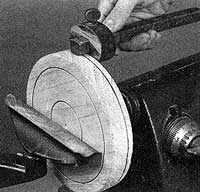
Round the outside diameter first. Use a gouge, just as you would for spindle turning, with this one exception: If the wood grains are perpendicular to the axis of rotation, do not attempt to shear. Scrape the workpiece round (Figure 12-42). Trying to shear will tear out large chunks of the stock. Shearing only works well when the wood grain is parallel to the axis of rotation.
Sizing
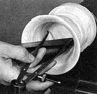
After the workpiece has been rounded, it should be marked to show the limits and the depth of shapes you wish to produce. With the machine turned off, work with dividers or a pencil compass to mark concentric circles (Figure 12-43), but be sure to use the tool rest for support. Use a light touch. You can use a marking gauge to mark dimension lines on the perimeter of the workpiece as shown in Figure 12-44.

Shaping
Most woodworkers prefer to turn the outside first (Figure 12-45). Make your beads and coves in the same manner as you would for spindle turning. If the wood grain is perpendicular to the axis of rotation, scrape the desired shape in the outside of the workpiece.
When you get ready to turn the inside of the work piece, turn the machine off. Let it come to a complete stop; then reposition the tool rest at 900 to the axis of rotation, about 1/4″ in front of the work piece. Adjust the height so that it’s about 1/4″ below the center of the work piece.
No matter what the orientation of the wood grain, scraping is the only way to shape the inside of a faceplate turning. This is slow work, so have patience. Select a round nose chisel, turn on the lathe, and slowly feed the chisel against the “down” side of the stock (Figure 12-46).
No matter what the orientation of the wood grain, scraping is the only way to shape the inside of a faceplate turning. This is slow work, so have patience. Select a round nose chisel, turn on the lathe, and slowly feed the chisel against the “down” side of the stock (Figure 12-46).
When doing deep hollowing jobs, keep adjusting the tool rest to provide good chisel support even if it means partially inserting the tool rest in the hollow being formed (Figure 12-47). As you continue the
hollowing operation, periodically check the inside diameter of the turning with “inside” calipers so that you don’t scrape away too much
stock (Figure 12-48). Stop scraping whenever you’ve removed as much stock as you want to cut away. Figure 12-49 shows a gauge you can make to check the depth of hollowing cuts. It’s just a dowel that passes through a hole in a “beam” and which is locked in place with a setscrew. Cut depths can also be checked by placing a straightedge across the face of the work piece and then measuring from it to the bottom of the cavity.
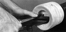
Figure 12-47. Always place the tool rest so the chisel will have maximum support even if on hollowing jobs it means inserting the tool rest into the cavity being formed.
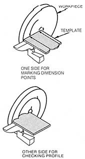
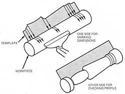
Templates, like those described for spindle turnings, can also be made for faceplate work (Figure 12-50). One side of the template is used to mark dimension points, the other side has the checking profile that you use to gauge the cuts you make. Templates are always a good idea when you must turn duplicate pieces.
Sanding
When you’ve finished shaping the turning, turn off the machine and let it come to a complete stop. Warning: Remove the tool rest before sanding a turning on the lathe.
You can remove the feathers either by wetting the wood or by removing the faceplate from the main spindle and remounting it on the upper auxiliary spindle (Figure 12-51). This reverses the direction of rotation.
Parting
To part a faceplate turning, first dismount the faceplate from the Mark V spindle and unscrew the faceplate from the scrap block. Clamp the scrap block in a vise and place a bench chisel against the joint between the block and the turning (where you’ve put the paper). Sharply rap the chisel with a mallet, driving it in between the block and the turning (Figure 12-52). The turning will part from the scrap block. Sand any paper or excess glue off the turning.
Other Special Techniques
There are many special techniques that can be performed on the lathe. Let’s take a look at some of the simplest:
Screw Center Work
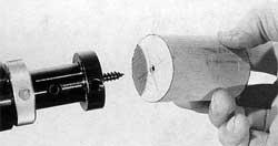
Workpieces that are too small to be mounted on a faceplate or not long enough to be fitted between centers can be set up for turning by using a screw center (a device that is mounted on the Mark V main spindle). Find the center of the workpiece and start a hole for the screw by using an awl or by drilling. Mount the workpiece by threading it on the screw center (Figure 12-53). The technique makes it possible to shape small items like drawer or door pulls, finials or small posts (Figure 12-54).
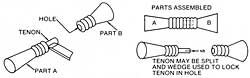
Extra-Long Work
When a project is longer than the spindle capacity of the lathe, it can be turned as separate pieces that are then joined in the manner shown in Figure 12-55. The tenon on the one piece can be formed while the part is on the lathe. Drill a matching hole in the mating piece; then put the parts together with glue. Use a Iockwedge, if you wish, to reinforce the joint.
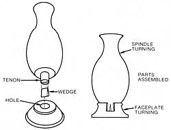
The same idea applies when you join a face plate turning to a spindle turning (Figure 12-56).

Glued-Up Stock
When a large diameter is required in one area of the turning, two methods are used to prepare the stock (Figure 12-57). In one, start with oversized stock and use a jointer or bandsaw to reduce the stock before it is mounted on the lathe. Warning: Glue the stock and leave it clamped for at least 24 hours prior to turning.
In the other, glued blocks are used to build up the larger diameter. The mating surfaces must be perfectly flat and true for a perfect joint if the final turning is to resemble a solid piece of wood.
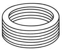
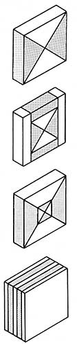
When solid stock large enough for a deep bowl or similar project is not available, stock may be glued together (Figure 12-58). Or rough-cut rings may be glued onto a solid base. This method saves a lot of material since the cutout discs may be used in other ways. Figure 12-59 shows rings cut for a project that will have straight sides. If the sides are to slope or taper, the rings should vary in size. The important thing is a good glue job so the stock will hold together with just a faint line showing on the finished item.
You can produce intriguing lathe projects with an inlaid appearance when you prepare the base stock by gluing together pieces of contrasting wood. The initial blocks can be prepared for either spindle turning (Figure 12-60) or faceplate turning (Figure 12-61). The blocks won’t look like much to start; the appealing effects occur when the turning is complete. It’s not easy, but try to visualize the results as you plan the initial block assemblies.
Select wood not only on the basis of color contrast, but also for similarity in density. Good combinations to try are maple with rosewood, and holly or birch with cherry, walnut, or mahogany.
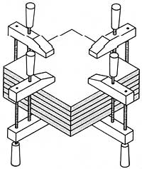
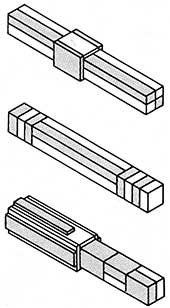
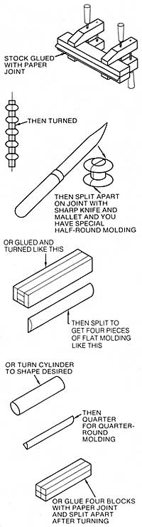
Split Turnings
Split turnings are lathe projects that end up as half-round, shaped columns. Using the paper-glue-joint method shown in Figure 12-62, two pieces of wood will produce identical half-round moldings. Four pieces of wood, paper-glued to a central core piece, will separate as elliptical moldings. Four pieces of wood, assembled as a solid block, will become four pieces of quarter-round molding. Warning: Glue the stock and leave it clamped for at least 24 hours prior to turning.
Procedures like this are useful when a special molding is needed or when you need a particular hardwood molding that isn’t available.
Select wood not only on the basis of color contrast, but also for similarity in density. Good combinations to try are maple with rosewood, and holly or birch with cherry, walnut, or mahogany.
Split Turnings
Split turnings are lathe projects that end up as half-round, shaped columns. Using the paper-glue-joint method shown in Figure 12-62, two pieces of wood will produce identical half-round mold-ings. Four pieces of wood, paper-glued to a central core piece, will separate as elliptical moldings. Four pieces of wood, assembled as a solid block, will become four pieces of quarter-round molding. Warning: Glue the stock and leave it clamped for at least 24 hours prior to turning.
Procedures like this are useful when a special molding is needed or when you need a particular hardwood molding that isn’t available.
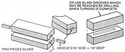
Through Holes
The two methods shown in Figure 12-63 can be used to prepare stock for projects like lamp bases before the material is mounted for lathe turning. Cut grooves in the center of the stock. A groove about 7/16″ wide by 7/32″ deep in each piece will do for lamp cords.
Glue the pieces together and use keys to plug the opening at each end. When the turning is complete, open the grooves by boring holes at each end of the turning.
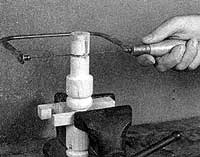
Accurate center holes, of limited length when using conventional bits or much deeper when working with extra-long bits or extension bits, can be formed by mounting the drill chuck on the tailstock. Figure 12-64 shows the technique being used to form a socket hole in a small candle stand. The procedure is the opposite of normal boring. Here, the drill bit is stationary; the workpiece turns.
Indexing
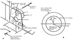
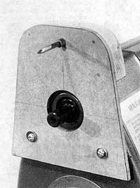
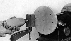
Some lathe projects, like wheel hubs, require radial holes that are equally spaced about their circumference. A good way to do such work accurately is to use an indexing device. The plans for one that you can make and which is mounted on the Mark V’s upper auxiliary spindle is shown in Figure 12-65. Make the guide pin holder first. Then drill holes in the power plant cover and mount the holder as shown in Figure 12-66. Drilling holes in the power plant cover will not damage the machine. You must situate the holder so the guide pin and the spindle have a common vertical center line.
Indexing
Some lathe projects, like wheel hubs, require radial holes that are equally spaced about their circumference. A good way to do such work accurately is to use an indexing device. The plans for one that you can make and which is mounted on the Mark V’s upper auxiliary spindle is shown in Figure 12-65. Make the guide pin holder first. Then drill holes in the power plant cover and mount the holder as shown in Figure 12-66. Drilling holes in the power plant cover will not damage the machine. You must situate the holder so the guide pin and the spindle have a common vertical center line.
The indexing disk, which is the control that positions a project for drilling, is made next. After the disk is cut out and rounded, mount it on a small faceplate. Then secure the faceplate on the auxiliary spindle (Figure 12-67). Push the guide pin forward so it will mark the disk. This will establish the radius of the circle on whose circumference the guide holes must be drilled. Make a layout and drill the holes. The plans suggests a spacing of 22-1/2°, but you can increase or decrease it.
A typical use for the indexing device and a drill guide are shown in Figure 12-68, where the hub for a wheel is being drilled for spokes. For example, if the hub is to have eight spokes, lock the indexing device at any point and drill the first hole. Turn the indexing device 45°, lock it with the pin, and drill the second hole. Turn the indexing device 45° for each hole until all are drilled. If the wheel needed four spokes, the device would be turned 90° to establish each hole position.

The drill guide, made as shown in Figure 12-69, is mounted in the tool rest arm and positioned so the bit will be square to the work and so its point will be on the work’s horizontal centerline.
Indexing, as shown in Figure 12-70, can also be used to gauge the spacing of surface-drilled holes. The drill guide can do double-duty. When you position it correctly, it will act as a stop to gauge hole depth.
Turning Small Components
Model makers will find a dowel turning fixture almost indispensable for small turnings like head-lights, wheel hubs, rims, capstans, deadeyes for boat and automobile models, and for making components for miniature furniture.
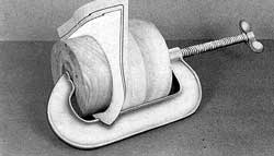
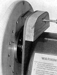
A good feature of the dowel turning fixture, shown in Figure 12-71, is that it allows mounting of a long piece of dowel that is gripped for turning with the drill chuck that substitutes for the usual drive center. The bolt acts as a tool rest. The table to which the fixture is clamped, or the power plant is moved to position the dowel for each new turning. The dowel doesn’t have to be cut until several individual parts have been formed.
To make the dowel turning fixture follow the plans in Figure 12-72. The plans show three sizes of holes, but you can accommodate other sizes of dowels merely by drilling additional holes.
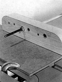
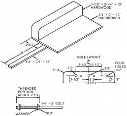
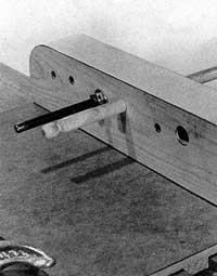
Figure 12-73. The bolt, which is part of the dowel turning fixture, serves as a tool rest. Apply paste wax to the dowel so it can turn with minimum friction.
Figure 12-73 shows the relationship between the dowel turning fixture and a turned dowel. It’s a good idea to coat the dowel with paste wax to minimize friction where the dowel turns in the block.
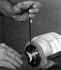
The dowel turning fixture can also position tiny work for concentric drilling. If the work is very tiny, it can be gripped in a router chuck locked on the main spindle.
Turning Ovals
The most important part of turning a cylinder into an oval shape is the initial layout on the ends of the stock.
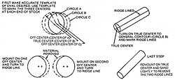
First make an accurate template for locating the true center and the two off centers (Figure 12-74). If the ridge line is located first, it is easy to position the template at the ends of the stock and mark the centers with an awl.
Turn the work on true center until it is round. Remark the ridge line.
Mount the work on one of the off centers. Turn it until the cut nears the ridge line. Now it’s round on one side, oval on the other.
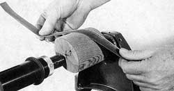
Mount the work on the remaining off center; turn it down to the ridge line. Now the work is oval. Sand it as illustrated in Figure 12-75.
Turning Spirals
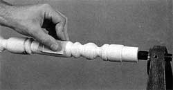
Spiral forming is classified as a lathe job even though most of the work is done by hand. It is started by mounting stock between lathe centers and turning it to a cylinder.
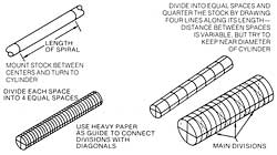
Layout of the spiral divisions is shown in Figure 12-76. First mark off the length of the spiral. Divide this into equal spaces, each approximately the diameter of the cylinder. Draw four lines along the length of the stock, connecting common perpendicular diameters at each end. Now divide each space into four equal parts and, with a heavy piece of paper as a guide, pencil-mark diagonal lines across each one as shown.
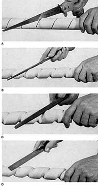
Now follow the sequence detailed in Figure 12-77. Use a saw to cut along the spiral line to the depth needed (Figure 12-77A). This depth is easily controlled if a keyhole saw is used. If a backsaw is used, clamp a block of wood to it to act as a depth guide. Next use a round file to form a groove to the depth of the saw cut (Figure 12-77B). Open up the groove with a square file (Figure 12-77C). Shape it with a half-round file (Figure 12-77D). Use sandpaper to do the final shaping and smoothing.