The Shopsmith Routing System is a home or small shop version of a commercial machine that was originally developed for high-speed mass duplication of furniture parts and components.
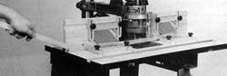
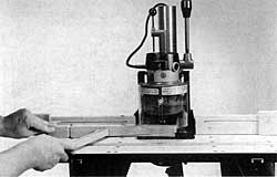
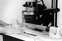
In the overarm mode of operation, a rigid arm holds a router motor securely in a fixed position over the table surface. The arm itself has a built-in quill-feed lever that controls the depth-of-cut.
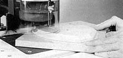
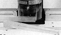
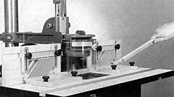
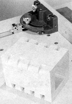
During the duplication process, the routing system suspends a router motor and bit above a precisely aligned pin which protrudes up from the table surface and rides in a precut groove in the underside of a guiding fixture. By guiding fixture. By guiding the fixture over the pin, the operator can cut the identical design or shape in a workpiece attached to the top (or opposite) side of the fixture.
In the under-table mode, the base of your router is attached to the underside of the table. When the router is installed in this manner, the router bit will protrude up through the table surface.
Besides the obvious time-saving benefits of high-speed duplication, the routing system also offers certain safety advantages by providing improved visibility and control of the work, as well as the ability to perform operations on smaller workpieces that would be almost impossible to grip firmly while using a hand-held router.
The routing system will cut-out, shape, mold, mortise, duplicate and form intricate, professional-looking joinery for a wide variety of projects.
Setup and Features
To set up your routing system, follow the instructions in the Owners Manual that came with your Routing System.
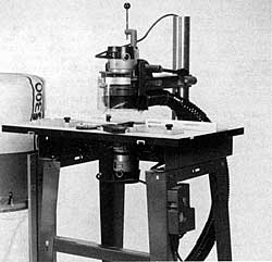
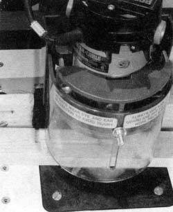
The Shopsmith Routing System (Figure 22-1) offers a number of unique features:
- In the overarm mode, the throat capacity of the routing system ranges from 13-5/8″ to 15-1/8″ (depending upon the diameter of the router motor being used).
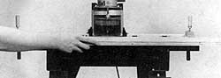
- By moving the arm to the top of the steel column, projects up to 12″ thick can be worked in either the overarm or under-table mode with ease.
- In the overarm mode, the arm holds any router motor from 2-1/2″ to 4″ in diameter firmly in position.
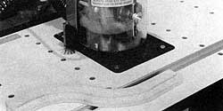
- For under-table routing, a universal table plate will accept virtually any router base for quick, simple mounting.
- The routing system’s precision rack-and-pinion vertical feed mechanism offers up to 3-1/2″ of vertical travel to provide easy depth-of-cut control during over-arm operations.
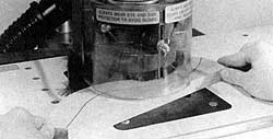
- A large see-through guard keeps your hands and fingers out of the danger zone, protects your eyes, and directs debris to a dust collection system.
- The worktable is 30″ wide by 18″ deep and offers over 7″ of front-to-back adjustment. It can be locked into position at any location. Its smooth, laminated surface offers a large number of threaded holes to enable the convenient attachment of optional feather boards, fences and other devices to improve workpiece control and safety during operations.
- The built-in miter rail allows the use of the Shopsmith Miter Gauge as a guide or safety device during operations.
- Interchangeable table inserts provide adequate workpiece support when using a variety of different sized router bits.
- Screw-in guide pins allow precision pin routing with a variety of bit sizes.
- The optional two-piece adjustable fence is used to guide workpieces during straight-line routing and for mounting fence ex-tensions and stop blocks
Router Bits
Router bits come in a large variety of shapes and sizes, each designed to preform a specific operation. Generally speaking, most router bits have three main components. These are the shank, the flute and the pilot (Figure 22-2).
The shank is the part of the bit that is gripped firmly by the collet (or chuck) of the router motor. The pilot is the portion that rides against the edge of the workpiece and controls the depth-of-cut of the bit during operations. The flutes are the cutting edges of the bit.
Figure 22-3. Router bits are available in piloted or unpiloted styles.
Piloted Versus Un-Piloted Bits
When buying router bits, you have the option of selecting either piloted or un-piloted bits (Figure 22-3).
Piloted bits are used when cutting a decorative profile on a straight or curved workpiece where the entire edge of the workpiece is not to be removed. When choosing piloted bits, you can select from bits with solid pilots or bearing pilots. Solid pilot bits are less expensive, but create friction that could burn your workpiece edge during cutting. Although bearing pilot bits are slightly more expensive, they will eliminate this friction and burning of the workpiece edge.
Un-piloted bits offer no edge guide and will cut all the way to the tip. They are therefore designed for use on projects where the entire edge of the workpiece is to be removed or a decorative cut is desired somewhere within the perimeter of the stock. As a result, they should always be used with a fixture, guide pin or fence.
Router Bit Materials
Router bits are available in a variety of different materials, based upon the amount of use they are expected to receive and the types of materials they are intended to cut.
High-speed steel bits are the most commonly available type and are intended for occasional use only, or for working with soft woods such as pine or redwood. These are the least expensive of all bits and offer limited use before sharpening is required.
Carbide-tipped bits generally offer high-speed steel shanks and bearing pilots with carbide cutting flutes welded-on to provide for more extended use before sharpening is required. Carbide-tipped bits should be used for working with hardwoods such as oak or maple, plastic laminates or composite materials like particleboard. These bits are slightly more expensive than high-speed steel bits.
Solid carbide bits are usually only available in simple, straight profiles and offer the same benefits of durability as carbide-tipped bits.
Router Bit Types
Router bits are available in many different shapes for a variety of specialized jobs. Figure 22-4 shows examples of the types that are available.
Mounting Router Bits
Always insert the bit all the way into the router’s collet and then back it out about 1/8″ before tightening to prevent the transfer of heat and vibration from the bit to the router motor armature.
Router Bit Storage
When storing router bits, never throw them carelessly into a drawer with other tools. This could result in nicking of the edges and necessitate costly, professional sharpening. In addition, avoid storing them in a damp location, as this will cause rusting (and dulling) of the edges. One suggestion is to store them in an enclosed area with camphor tablets (which coat the bit with a thin, rust-inhibiting film).
Cleaning Router Bits
Occasionally, router bits will col-lect pitch that should be removed to prevent burning of the work-piece edges. This cleaning can be easily performed with household oven cleaner. However, always remove bearing pilots from bits to avoid getting solvents or oven cleaner in the bearings. These materials will destroy the bearing lubricant and cause premature bearing failure.
Sharpening Router Bits
As with all cutting tools, router bits require occasional sharpening for optimum performance. High-speed steel and carbide-tipped bits can be easily honed in the shop. However, if carbide-tipped or high-speed steel bits become extremely dull or nicked, they should either be replaced or taken to a professional sharpening service.
Routing System Safety
Warning: Before using the routing system, read and understand these important safety instructions:
Danger Zone-The danger zone on the routing system includes any location within 3″ of the rotating bit. Always keep hands clear of this area when working with the machine.
Protective Guard-Keep the seethrough guard in place and set at no more than 1/4″ above the surface of the workpiece during overarm or undertable routing.
- Always wear proper eye and ear protection.
- Never attempt to clamp the overarm assembly onto any column less than 2-3/4″ in di-ameter by using bushings or adapters.
- Follow your router manufacturer’s recommendations as to replacement parts for your router.
- Before beginning any operation or turning on your router motor, always check to be sure the router, overarm assembly, depth stop rod, depth control handle, worktable, table plate, accessories, safety devices, fences and fixtures are secured.
- Whenever possible, use a push stick, push block, feather board, miter gauge with safety grip, fixture or other safety device to maneuver a workpiece into the rotating bit. This is especially true of small or narrow stock.
- Always keep a firm grip on your workpiece and never hold it with your hand in line with the bit.
- When cross-grain routing stock up to 10″ wide, use your miter gauge with safety grip to control the workpiece (which must extend 5-1/2″ away from the router bit).
- To prevent the router from grabbing and throwing the workpiece, always feed the stock against the rotation of the bit and never with it. During overarm routing, stock being worked in front of the bit should be moved from left to right. During under-table routing, stock being worked in front of the bit should be moved from right to left.
- Always cut with the grain of the wood and not against it for a smoother, safer cut.
- To avoid being hit by a thrown workpiece, never stand in-line with the workpiece being fed.
- Never rout second-hand lumber. It may contain nails or screws that could damage your bit and cause serious injury.
- Use extra care when work-ing stock that contains highly figured grains or knots to avoid kickbacks.
- Do not rout boards that are warped, bowed or cupped.
- When working long boards or sheet materials, always sup-port them adequately with roller stand(s) placed from 1′ to 4′ from the table.
- Never freehand rout stock less than 12″ x 12″ in size or equivalent.
- With the exception of single-pass dovetail cuts, limit your depths-of-cut to 1/4″ for each pass when using bits up to 1/2″ in diameter to cut hardwoods.
- Never exceed depths-of-cut of 3/8″ when using bits up to 1/2″ in diameter to cut soft woods.
- When using bits over 1/2″ in diameter, limit your depths-of-cut to half the recommended depths for bits up to 1/2″ diameter.
- NEVER feed your workpiece between the rotating router bit and a fence, as this could cause a kickback.
- When stop routing, always use stop block(s) to control the length of cut. Failure to use stop block(s) could cause a kickback.
- NEVER install a router bit without first unplugging the router motor.
- Make sure the router bit is secured firmly in the collet. Loose bits could work free and cause serious injury.
- Insert bits all the way into the collet and retract them about 1/8″ to avoid transferring vibrations and heat to the motor armature.
- Listen carefully for sounds of chattering or looseness at start-up. If you hear, see, or suspect problems, turn off the tool immediately, unplug it and check it out thoroughly. Correct the problem before proceeding.
- NEVER try to make your own collet adaptor to hold different sized bits. Balance is very important at high speeds, so always use purchased adapters.
- Keep router bits clean and sharp at all times.
- Attach the routing system to a dust collection system . . . or wear a close-fitting dust mask.
Special Cautions and Considerations on Materials and Techniques
Because routers are powerful, high-speed tools with unique performance characteristics, you must pay particular attention to the materials and techniques you are using to avoid mistakes and safety hazards.
- All hardwoods should be worked in light, multiple passes without pausing or dwelling to avoid burning the workpiece. Open grained hardwoods such as oak and similar species will splinter very easily when you reach the end of a crossgrain cut. For this reason, it’s always a good idea to either make very light passes, leave extra stock on the width of the workpiece so the splintered area can be cut away or backup your workpiece with a scrap block at the exit point of the bit. Another good technique to avoid splintering is to make all cross-grain cuts first, then make your cuts with the grain.
- Softer woods such as lauan, basswood, pine and willow can be worked in slightly heavier passes but “tear” or “fuzz” easily and will require more finish sanding.
- Highly figured woods such as birdseyes, crotchwoods and burls have an inconsistency of grain that requires cautious, light passes to produce a clean cut.
- Particleboard and similar composite materials contain high concentrations of glue that can quickly dull high-speed steel bits. Therefore, it is recommended that you always use carbide-tipped or solid carbide bits when working these materials.
- Plastic laminates are very hard materials that can also dull high-speed steel bits quickly. Again, always use carbide-tipped or solid carbide bits when working laminates.
- Avoid pressing hard against the bearing pilots on certain bits during cuts. Since they rotate at such high speeds, excessive friction could cause a heat build-up that will destroy the bearings.
- Again, it’s important the stock always be fed into the rotating bit and not with it to avoid kickbacks.
Routing System Operations
You can perform both overarm and undertable operations with your routing system. Overarm operations will be explained first, followed by undertable operations.
Edging
This process is used most frequently in the construction of furniture and cabinetry. And although the shaper is an excellent tool to use for the job, the high operating speed of the routing system can often produce cuts so smooth that they will seldom require sanding.
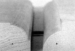
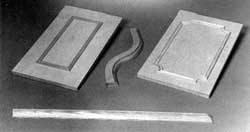
To begin, there are two types of edging operations (Figure 22-5).
Full Edge Removal-First, there’s the type where the entire edge of the workpiece is removed.
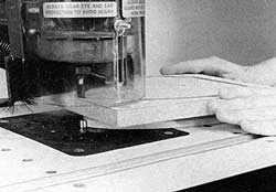
This operation is performed with unpiloted bits and requires the use of a fence (Figure 22-6) or guide pin to limit the depth-of-cut and keep it consistent along the entire edge.
When working projects with straight edges, it’s best to use a two-piece fence or a guide strip to control your depth-of-cut.
Remember that if you’re using a two-piece fence for this operation, the infeed side of the fence is adjusted to control the depth-of-cut while the outfeed side is adjusted to provide support for the stock after the cut has been made (Figure 22-7).
Keep in mind that in order to remove the entire edge of a workpiece, the bottom cutting edge of the bit will have to protrude below the workpiece.
To perform this operation without routing into the top surface of the table, be sure to position the table so the bit protrudes down through the hole in the table plate or the table insert during operations.
When working against a fence, always make the cross-grain cuts first, followed by the with-the-grain cuts to cut away any tearouts or splintering. Don’t try to make your cuts in a single pass. Always take multiple passes to achieve the cleanest cuts.
When removing an entire edge on a round project such as a plaque or wheel, you can control the depth-of-cut by drilling a shal-low hole in the center of your circular workpiece (on the back side) that can be dropped over an offset guide pin or the starter pin and used as a pivot to rotate the stock through the cut (Figure 22-8).
The final way to control the depth-of-cut when removing the entire edge of a workpiece is with a fixture. This process will be explained later in the chapter.
Partial Edge Removal-This is the simplest of all edging operations since it is usually performed with piloted bits that control the depth-of-cut during operations on straight or irregular-shaped workpieces.
If you’re using a piloted bit, fences and fixtures are not necessary. Just ease your workpiece into the cut by resting it against the 1/4″ starting pin, then guide it against the bearing or solid pilot of the bit (Figure 22-9).
If you want to remove only part of the workpiece edge and have no piloted bits, you will have to use fences to control your depth-of-cut on straight-edged projects.
In those cases where you’re using unpiloted bits on circular or irregular shaped stock, simply use an undersized guide pin to control your depth-of-cut. The guide pin should be centered under your bit during this operation. Then, merely press your stock firmly against the pin as you rotate it through the cut. The depth-of-cut can be changed by altering the size of the guide pin (Figure 22-10).
Decorative Surface Cuts
Decorative surface cuts are best described as grooves or patterns formed on the surfaces of workpieces. Some examples might be “carved” house number signs, fancy kitchen trivets and accent cuts on cabinet doors (Figure 22-11).
Usually, decorative cuts are made with unpiloted roundnose, core box, veining or straight bits. As a result, you will need some way to guide your workpiece through the cuts. If your designs are straight and parallel with the edges of the workpiece, use the two-piece routing system fence. If they’re angled across the surface like those on the trivet shown in Figure 22-11, you will have to use a scrap piece of stock as a guiding fixture to “carry” your workpiece through the cuts. Simply attach your workpiece to this piece of stock with double-stick tape or nails. Then, guide this fixture (with your workpiece attached) against the fence to make your cuts (Figure 22-12). Warning: If you use nails to attach your stock to the guiding fixture, be sure they are not in the path of the bit.
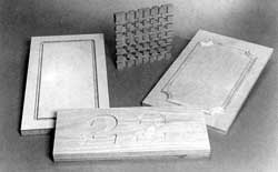
Figure 22-11. Decorative surface cuts like these are made with the routing system.
You can also use unpiloted edging bits such as an ogee or corner rounding bit to form fancy grooves in workpiece surfaces with shaped cuts on both the left and right of the bit (Figure 22-13). This technique can be used quite effectively to produce raised panel-looking cabinet doors from a solid piece of stock.
If you’re cutting grooves on the surfaces of round workpieces, you can use V-shaped fence faces (Figure 22-14) to guide the stock or use the pivoting pin technique described earlier under “Full Edge Removal”.
When making free-hand decorative cuts on irregular-shaped workpieces, it’s important that you take multiple light passes to avoid grabbing and provide improved control.
The most accurate method of forming irregular-shaped decora-tive cuts is with a guiding fixture. Specific information about making and using fixtures can be found later in this article.
Moldings
The process of making moldings on the routing system is very similar to the way it is done with the shaper. These finished moldings can be used in many different ways to accent all types of projects (Figure 22-15). Begin with a piece of stock that is large enough to handle safely. If your finished piece of molding will be straight, simply guide your stock against the pilot of the bit or a fence to form the edge, as you would for edging as explained earlier in this chapter.
Shop-made hold-down fences (Figure 22-16) will allow the use of feather boards in providing improved workpiece control during operations (Figure 22-17).
f your finished molding will be curved, first cut out the curved shape on a wide piece of stock (Figure 22-18). Then shape this curved edge on the routing system (Figure 22-19). Remember that if you’re using a piloted bit, no fixtures or fences will be required, since the pilot of the bit will control your depth-of-cut during operations.
If you’re using an un-piloted bit, you will need to use the fence when cutting straight moldings-a fixture (details provided later in this chapter) or an undersized guide pin (as explained under edging earlier in this chapter) when cutting curved moldings.
Once you’ve formed the shaped edge (curved or straight), simply cut it away from your workpiece using a bandsaw or scroll saw (Figure 22-20) and complete the operation by sanding the edges.
Mortising
Mortises are most commonly used for joinery in cabinet projects. However, there are other applications such as hinge mortises, inlay work and hollowed-out boxes of all types.
Hinge Mortises
As a rule, most hinge mortising is performed with a chisel. And, if you’re mortising for hinges on the edges of wide or large doors, this is still the best method because workpieces that are wider (or thicker) than 12″ will not fit between the table surface and the router bit. However, if you have a lot of mortises to cut in the surfaces of cabinet doors or similar projects, the routing system can make them quickly and accurately.
First, locate the positions of the hinges on the door surfaces and mark them very carefully. If you’re working with small doors or box lids, simple shop-made fence ex-tensions and stops can be attached to the routing system fence to limit your cuts in both directions. Make the fence extensions and stops as shown in Figure 22-21. When working with larger doors or lids that extend beyond the edges of the table, simply clamp the stops to the door or lid itself (Figure 22-22).
Measure the thickness of the hinge very carefully. Make your initial cuts with the smallest diameter straight bit you have so the corners will be as close to square as possible. Set the depth-of-cut of your bit to match the thickness of your hinge and make a test pass on a piece of scrap to verify the proper depth-of-cut.
Make all the cuts around the outer edges of your mortise (full depth) with the small bit (Figure 22-23). Then, remove the remainder of the stock from your mortise by changing to a larger diameter bit or by rocking your workpiece back and forth against the small diameter bit, using the stops and the fence extensions to limit your cuts. When you’ve finished, square all corners with a chisel and insert your hinges.
f you’re cutting mortises for odd-shaped hinges or hardware, it’s often best to do this free hand. First, trace the outline of the hinge onto your workpiece. Then, carefully rout away the stock in the center of your mortise, being sure to stay about 1/16″ to 1/8″ away from the outer cutline. Finally, rout away the remainder of the stock to complete your mortise. Note: Trace the profile of the mortise onto your workpiece with a razor knife. Then, darken the line with a pencil. As you make your final cuts to the profiled edge of the mortise, the router bit will turn up a fuzzy wood burr at the edge of the cut that will fall off as the bit reaches the line.
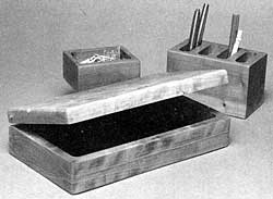
Making Mortised Boxes The routing system is perfect for making all types of mortised-out boxes for jewelry, pencils, etc. (Figure 22-24).
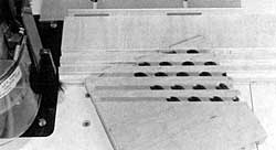
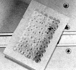
The techniques used here are very similar to those used for mortising hinges. However, since boxes usually require that a lot of stock be removed, it is suggested that you start by doing this with brad-point bits or forstner bits on the drill press (Figure 22-25).
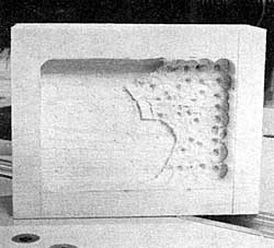
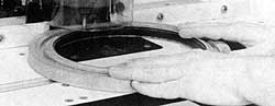
When you have finished this process, cut out the scrap with a bench chisel and clean-up the edges and bottom with a router bit (Figure 22-26).
For this job, you can use either a straight bit or a special 3-in-1 bit, which forms a flat bottom, straight sides and a coved edge where the bottom and sides meet.
To control the cuts, use the fence extensions and stops, much as you would with hinge mortises.
Joinery
The overarm mode of the routing system is an excellent way to make a wide variety of structural joints for cabinets and furniture projects of all types (Figure 22-27).
The router bit’s high operating speed allows it to make cuts that are cleaner than those produced by a table saw. And in some cases (like the mortise for a mortise and tenon), it will perform operations that simply cannot be done on the table saw.
Generally, most joints are formed by using un-piloted straight bits with the workpiece being guided by a fence, miter gauge and/or stops to control and limit the depths-of-cut. This capability provides the advantage of repetition, ensuring that every cut will be identical to the last.
As with other routing system operations, it’s often best to back up the exit sides of through cross-grain cuts with scrap blocks (or to allow sufficient extra stock so that some can be removed after the initial cuts are made) to prevent unsightly tear-outs.
In some cases (such as square-cornered mortise and tenons), the corners of the joints will require squaring with a chisel after they’ve been cut. However, if you’re producing a rounded mortise (which is perfectly acceptable in most cases), you’ll have to round the ends of the matching tenon with a file or pocketknife to match the mortise. Another option is to cut the tenon shorter so its square corners will slip inside the rounded ends of the mortise.
Duplicating
Of all the unique capabilities provided by the overarm mode of the routing system, high-speed duplication of complete projects or project components is the most interesting and challenging.
Through the use of shop-made guiding fixtures, you will be able to make an unlimited number of identical pieces, quickly and accurately.
As we explained briefly in the beginning of this chapter, the process works by guiding a pre-cut fixture over a pin which protrudes up from the routing system table surface. When a bit is installed directly above the pin (and in perfect alignment with it), a matching pattern is cut into a workpiece attached to the opposite side of the fixture (Figure 22-28).
Types and Styles of Fixtures
There are two types of fixtures that can be used with the routing system: permanent and temporary.
Permanent Fixtures are more complicated in their design and allow for rapid attachment and removal of workpieces in a repetitive fashion. They are generally used when making five or more of the same project or component.
Temporary Fixtures are usually nothing more than a wooden template of a simple design that is merely screwed to your workpiece. Temporary fixtures often require more time to attach and remove the workpieces than permanent fixtures. This is perfectly acceptable since it makes little sense to spend a lot of time building a complicated fixture that will be used to produce less than five identical projects or components.

When making fixtures, it’s important to think about how many times they will be used before deciding how the workpiece will be held in position. If you’re planning to make a large number of the same piece, you will want a fixture that allows the rapid attachment and removal of stock. If you’re only making one or a few of the same piece, this is less important.
There are a number of different styles of fixtures, determined by the way the stock is held in position and whether you are cutting on the outside, inside or both edges of your workpiece:
Screw-on Fixtures (Figure 22-29) are among the simplest in design. With this style, screws are driven up from the underside of the fixture and into the workpiece to hold it firmly in position during operations. If you have a power screwdriver or variable-speed reversible drill with screwdriver bits, this attachment style works equally well for both temporary and permanent fixtures and is a “must” if you are removing the outside edge of your workpiece.
Drive-on Fixtures (Figure 22-30) feature screws driven up through the bottom of the fixture so they protrude 1/8″ to 1/4″ above the top surface. The work-piece is positioned on top of the fixture and struck with a hammer or your hand to temporarily “impale” it on the protruding screw points. This attachment style is also ideal for either permanent or temporary fixtures and is a good option when removing the outside edge of your workpiece. Always use sheet metal screws for these fixtures, since they have threads all the way down the shank. Once you’ve driven the screws through the fixture, sharpen the protruding points with a file.
Clamp-in Fixtures (Figure 22-31) are the most complicated style, yet offer the distinct advantage of quick workpiece attachment and removal. Since they require more time to build than any of the other types, they are usually reserved for situations where you will be cutting-out large numbers of the same item. With these fixtures, the stock is clamped firmly in position during operations by a “floating” bar or cam clamp. Since the workpiece is gripped by the edge, this style of fixture will not allow full-depth cuts around the outside perimeter of the stock.
Drop-in Fixtures (Figure 22-32) are made the same way as clamp-in fixtures, but have no bar or clamps to hold the workpiece in position. Instead, the stock is merely dropped into the frame and cut as it would be
with a clamp-in fixture. Warning: A tight fit of the workpiece is critical to keep it from moving during operations. Again, these fixtures are recommended for high-volume situations and not for projects where full-depth cuts around the perimeter of the stock are required.
Profile Fixtures are usually a combination of drive-on and drop-in styles (Figure 22-33). The most common application for these is the making of fence post tops and similar projects. They usually contain sides to help position the workpiece and protruding screw points to keep it from moving during operations. However, they can also be made with floating clamp bars or eccentric clamps, if you like. If the profile is identical on both sides of the workpiece, the fixture can be profiled on one side only and the stock flipped over to cut the second side.
Double-Stick Tape Fixtures (Figure 22-34) are very simple to make and work very well when the workpiece must be cut around the perimeter and is too thin to grip from below with screws. They can be made with readily available double-stick tape and should only be used when the stock is large enough to hold firmly in position with your hands a safe distance from the rotating bit. They are intended primarily for low-volume production jobs. Warning: Change tape frequently, since wood dust and repeated use will cause its adhesive qualities to fail after a few uses.
Building Fixtures
For reasons of durability, most fixtures are made from particleboard or other similar materials that are covered with plastic laminate. These materials will withstand long periods of continuous use without wearing down and changing the profile of your pattern. This type of material is readily available from cabinet shops and hardware stores as cut-outs for sinks from countertops and is usually very inexpensive.
If laminate covered particle-board is not available in your area, it is suggested that you use hardwoods such as oak, maple or cherry. . . or a high-quality plywood without any “voids” or holes in the edge grain. Remember, the key to building a long-lasting fixture is to make it with durable materials that will withstand long periods of continuous use without wearing and altering your desired profile.
There are two basic ways to build routing system fixtures: us-ing an existing product or using a template.
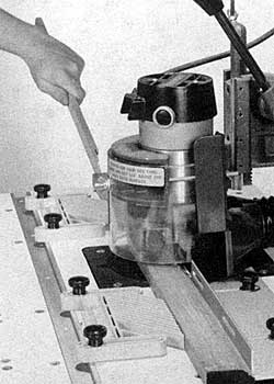
Using An Existing Product-The first and easiest way to do this is to start with an existing product and use it as a template to guide your bit through the process of cutting the grooves in your fixture blank.
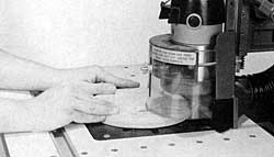
To begin, cut out a fixture blank that is 1″ to 2″ larger than the dimensions of your item. Start by drilling countersunk pilot holes for the holding screws in the existing item. Then, attach the item to be duplicated to the particleboard side of your fixture blank with screws or nails (Figure 22-35). Be sure to position the attaching screws or nails in a location where they will not be seen or be in the path of the router bit when you make your cuts.
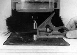
Next, select the size straight bit you will be using to make your profile cuts (usually a 3/8″ straight carbide bit) and thread the matching pin into the center hole of the pin insert in the table. Align the pin and bit perfectly by using the base of a combination square (Figure 22-36) or a guide block with a same size (3/8″ in this case) through-hole (Figure 22-37).
Once the machine is aligned properly, set the depth-stop rod to make a cut about 3/8″ deep in the surface of the fixture.
Once the machine is aligned properly, set the depth-stop rod to make a cut about 3/8″ deep in the surface of the fixture.
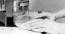
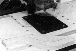
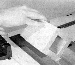
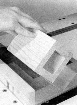
Turn the fixture over with the product to be duplicated on the bottom and start your router motor. Slide the fixture forward until the guide pin touches the edge of the product and lower the rotating bit into the laminate material about 1/8″. Twist the quill feed handle to lock it into position.
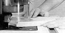
Guide the product around its profile (against the rotation of the bit), being sure to always maintain contact with the guide pin during operations (Figure 22-38). Repeat this process two more times until you have cut your groove in the laminate surface of your fixture to a depth of about 7/16″ to 1/2″. Remove the existing product from the fixture. To make dupli-cates of this product, simply screw a blank workpiece to the particleboard side of the fixture, drop the groove in the laminate side of the fixture over the protruding table pin, and make your profile cuts. It’s that simple! Note: By cutting another groove (shown with broken lines in Figure 22-29) in the fixture, you can also cut out a plaque-shaped picture frame, as well as a smaller plaque, all at once.
Using A Template-A template is a wood or plastic shape that is mounted to the fixture blank and used as a guide to cut the grooves in the fixture blank when making a fixture.
To make a template, first trace the desired shape onto a piece of stiff paper or cardboard to create a pattern (a pattern is the paper or cardboard “master” of your shape that is then traced or glued onto the template blank).
Then, cut out the shape of the design and trace the pattern onto a 1/2″ thick piece of plywood or plastic. Once the pattern is traced onto the template blank, cut out the shape with a scroll saw, bandsaw or sabre saw. Remember that the grooves in your fixture will only be as smooth and perfect as the template you use to cut them with . . . so take extra care in cutting out and sanding the template so that it’s as perfect as possible. Note: When building or working with intricate-shaped projects, it’s a good idea to use the original template to trace the pattern of your project on your workpiece (or, when making your fixture, on the top side of the fixture) so you can clearly see each area as it is being cut.
Next, use screws or nails to affix the completed template to the particleboard side of a fixture blank that is slightly larger than the design. Warning: Be careful not to locate screws or nails in the path of your bit.
Insert and align the matching bit and guide pin. When cutting out designs with tight curves, you may have to use a bit and pin combination that is smaller than 3/8″.
Turn your fixture over with the template on the bottom, set the depth-of-cut as described earlier and turn on the router motor.
Ease your pattern towards the pin until it makes contact, lower the rotating bit into the laminate side of the fixture and cut the grooves to a depth of about 7/16″, as described previously for making a fixture from an existing product.
If your template is intricate with lots of cut-outs, you will have to move your bit from cut-out to cut-out, raising and lowering the bit for each one. Note: If a cut-out is wider than the diameter of the pin and bit you are using, you must always maintain firm pres-sure against the pin while you guide the template through the cuts. If you allow the fixture to switch from one side of the cut-out to the other during operations, your fixture groove will become wider than the bit and could cause a loss of precision and a rough cut when duplicating your workpieces.
mportant Tips on Building Fixtures
Screw-on Fixtures–Caution: Be sure to countersink al/screw heads on the laminate side of your fixture soit will glide smoothly across the routing system table without marring the table surface.
Warning: Be certain all hold-down screws are located in areas that are not in the path of the router bit.
Drive-on Fixtures-Once the screws are positioned in the fixture, sharpen the points with a file to make it easier for them to grip your workpiece.
To ease insertion and removal of workpieces, drill a 1″ diameter hole in the fixture bottom (away from the path of the router bit during cutting) to allow you to push the workpiece out after it is cut.
Clamp-in Fixtures-After you have cut the guiding grooves in the fixture base, attach 3/4″ thick side and end rails to the base with screws and glue. Be sure the sides stick up above the base the same distance as the thickness of your project workpiece.
If your fixture has a floating bar to hold your workpiece, use T-nuts set into counterbored recesses and thumbscrews to apply adequate pressure against the floating clamp bar to hold the workpiece during operations (Figure 22-39).
An alternative to the floating bar clamping system is eccentric cams that can be rotated 1/2 turn or less to grip the workpiece tirmly (Figure 22-40).
Drop-in Fixtures-For extra holding power, you can add protruding drive-on screw points to drop-in fixtures.
To ease insertion and removal of workpieces, drill a 1″ diameter hole in the fixture bottom (away from the path of the router bit during cutting) to allow you to push the workpiece out after it is cut.
All Fixtures-When making a fixture that contains small areas where all stock is to be removed (and the scrap will not be held in position by screws), remove all stock from this area on the fixture, as well. This will allow you to rout out the entire area in shallow passes and prevent the scrap from grabbing when you cut out your workpiece.
Valuable Tips for Working with Fixtures
- Wax the laminate side of fixtures frequently to help them glide smoothly over the table surface.
- Clean the sawdust and debris out of the pattern grooves of your fixture occasionally to prevent jamming and help keep the fixture operating smoothly.
- If a fixture is expected to be used in a production environment for making a large number of the same item, use your original “master” fixture to make one or two more fixtures before it has a chance to wear out and lose its accuracy.
- When cutting out workpieces with a fixture, never allow your bit to cut into the particleboard side of the fixture more than 1/32″ to 1/16″.
- If you occasionally need to reduce the size of a project made on a fixture by a small amount, this can be done by using a smaller guide pin and a larger bit when cutting out your workpiece. Remember to work carefully and always guide your stock against the outside edges of your fixture grooves when doing this.
- If the edges of your project must be shaped after the profile is cut out, this can be done with the workpiece still attached to the fixture by merely switching bits (Figure 22-41). By changing to a smaller guide pin, you can alter the profile of your decorative cut…but remember to always guide your fixture against either the outside or the inside edges of the grooves during this entire operation. If you switch groove sides in mid-cut, you will change the shape of your decorative cut.
- If you will be making a large number of the same project with shaped edges, it’s a good idea to make several identical fixtures so you won’t have to keep changing from a straight bit (for making cut-outs) to a profiled bit (for shaping the edges).
Repairing Furniture and Veneers
The routing system is the ideal tool for repairing damaged furniture and veneers (Figure 22-42) if the damaged piece is small enough to work on the surface of the table.
To accomplish this task, first rout out the area to be repaired by guiding the damaged piece against a fence. Be sure to use a straight bit large enough to remove an area slightly larger than the damage (Figure 22-43).
Figure 22-43. Using a fence or guide strip, rout out an area slightly larger than the damage.
If you’re working with a solid wood piece, cut all the way through the stock to form an elongated hole in the wood. If you’re repairing a veneered area, be careful to cut no deeper than the veneer.
If you have cut a through-hole in the piece to be repaired, position a piece of wood of approximately the same grain pattern under the hole and trace the shape onto it.
If you have cut only to the depth of the veneer, lay a piece of tracing paper over the cut-out area and trace the shape onto it. Then, using carbon paper, trace the shape onto the piece of stock you plan to use as a plug…being careful to make this tracing about 1/32″ to 1/16″ larger than the actual cut-out.
Next, using a scroll saw or bandsaw, cut the plug out of your workpiece (Figure 22-44).
Using a disc sander with the table tilted about 5°, carefully sand around the edges of your plug. By tilting the table, your plug should be slightly smaller at the bottom than it is at the top. This will allow the plug to drop into the damaged cut-out easily.
Now, test the plug for fit. If it is too large, keep sanding around the edges until it drops into the routed-out area snugly. Once the piece fits, glue it into position.
After the glue has dried, sand off any protruding stock (on both sides) and stain the plug to match (Figure 22-45). If there are any voids left by the taper of the plug on the back side, fill them in with wood putty or plastic wood before staining.
Fluting
Fluting is a series of decorative cuts that are made with a core box or veining bit to enhance flat-sided or cylindrical posts and legs (Figure 22-46).
Flat Sided-Fluting of flat-sided (square, hexagonal, octagonal, etc.) legs and posts is a fairly simple matter.
Begin by setting up the fence and the fence extensions (Figure 22-21) to control the location of the flute. Then, firmly attach the stops to the extension fences to limit the length of the flutes (Figure 22-47).

Install your bit and set the depth stop rod to the depth-of-cut you desire.
Position your workpiece at one end of its intended travel and turn on your router motor. Slowly lower the bit into the stock and slide the workpiece against the fence extensions until the stop stops it. Raise the bit and turn off the router motor. Do not dwell or pause at either end of the cut or you will burn your workpiece.
Flat-Sided with Taper-Fluting flat-sided legs or posts with a taper is slightly more involved. Begin by cutting a tapered “wedge” to make the top (or working) side of the leg or post parallel to the table surface during operations (Figure 22-48). Temporarily affix the wedge to the flat on the opposite (or bottom) side of the stock that you plan to flute with masking tape or double-sided tape. Place the stops in position and proceed as you would for fluting flat-sided projects.
Cylindrical-If you are planning to flute cylindrical legs or posts, you will need to build a special indexing fixture to hold the work-piece during the cuts (Figure 22-49).
Begin by inserting the workpiece between the two centers of the fixture. The top of the workpiece must be parallel to the table surface. Attach stops to the routing system fence and/or the bottom or sides of the indexing fixture to limit the length of your cuts as described under fluting flat-sided workpieces.
Next, decide how many flutes you want around the circumference of your workpiece. The indexing head is set up to cut up to 24 flutes, 150 apart. If you want eight flutes, simply index the head three holes for each flute, insert the nail, and make your cut. If you want six flutes, index the head four holes for each cut, etc.
Make your passes just as described earlier for fluting flat-sided legs or posts, guiding the fixture with the workpiece in position through each cut (Figure 22-50).
Cylindrical with Taper-If your cylindrical legs or posts are tapered, use a “wedge” between the bottom of the fixture and the table surface, just as you would for fluting flat-sided workpieces with a taper.
Using A Drill Press Vise To Hold Workpieces
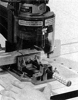
n some cases, you may have a workpiece that cannot be held properly for making cuts on a flat table surface or against a fence. An example of this could be cutting a mortise in a leg using a drill press vise (Figure 22-51).
To accomplish this task, make a sliding table to hold your vise like the one shown in Figure 22-52. Also use the fence extensions and stops (Figure 22-21) to control the length of the cut.
Under-Table Operations
Many of the operations that have been explained in the overarm operations section of this chapter can be performed with equal ease in the under-table mode.
However, because the rotating bit is not always in plain view during under-table routing, extra care should be taken at all times when in the under-table mode.
Warning: Whenever possible, use piloted bits, fence, fence extensions, miter gauge or other guiding devices during under-table routing. NEVER press directly down on top of your workpiece during under-table routing. If your workpiece should break, your hand could slip into the rotating bit, causing serious injury. ALWAYS use a push block, push stick, feather board or other safety device to exert downward pressure on the workpiece during operations. The bit is often not visible during under-table operations, therefore extreme caution is necessary.
Edging
Although most of the same rules apply to both overarm and under-table edging, the bit is often not visible during under-table routing and therefore, it’s even more important that you always use the fence, fence extensions, miter gauge and/or guiding device during under-table operations.
In addition, keep in mind that during under-table routing, the bit is rotating in the opposite direction as during overarm operations. Warning: The stock must always be fed from right-to-left during under-table routing.
Full Edge Removal-Since full edge removal requires the use of an unpiloted bit, under-table edging should be restricted to straight-edged or round workpieces. Either of these can be handled safely with the aid of a fence, miter gauge, or other guiding device.
However, since odd-shaped workpieces cannot be controlled with fences or other devices and the operator cannot always see the cut as it’s being made, full edge removal on odd-shaped workpieces should be performed only in the overarm mode and with a proper guiding device. Warning: Do not use the under-table mode to remove the full edge from an odd-shaped workpiece.
Partial Edge Removal-Because of limited bit visibility during operations, partial edge removal in the under-table mode should always be performed with piloted bits or with the aid of a fence, miter gauge, or other guiding device to control the depth-of-cut.
When performing operations on straight-edged or round work-pieces, use a fence, V-shaped fence faces or piloted bits. When working with odd-shaped project components, always use piloted bits to control your depth-of-cut.
Decorative Surface Cuts
If your decorative surface cuts are to be made in a straight line and will go all the way across a work-piece from one side to the other (no stopped cuts), they can be performed in the under-table
mode with the aid of a fence, miter gauge or other guiding device.
Because of limited visibility, making decorative stopped cuts in the surfaces of workpieces is not advised in the under-table mode of operation. These cuts are best performed in the overarm mode, where the workpiece and bit can both be kept in plain view at all times.
Moldings
The process of making moldings in the under-table mode is very similar to that discussed earlier in this chapter for the overarm mode, with a couple of important exceptions:
First, remember that with under-table operations, the bit pushes up on the workpiece instead of down. Therefore, when cutting straight moldings, the use of feather boards is essential (Figure 22-53). To use feather boards, you will have to construct hold-down fences (Figure 22-16). Warning: Be sure your stock is held firmly down against the table surface and inward, against the hold-down fences. With small work-pieces, be sure to use shop-made wooden push sticks for added safety. Because the bit is not always in plain view, when making Irregular-shaped curved moldings in the under-table mode, always use piloted bits.
If your curved moldings are round, use V-shaped fence faces like those shown in Figure 22-14.
When making curved moldings, proceed as you would for overarm routing. First, form the edges on an oversized piece of stock. Then, cut your molding away with a scroll saw or bandsaw and sand the sawn edges smooth.
Joinery
With the exception of mortise and tenon joints, virtually all of the structural joints shown in Figure 22-27 can be formed with the routing system in the under-table mode. In fact, some of these joints (such as tongue and groove and splined joints) are actually easier and safer to form in the under-table mode than they are in the overarm mode.
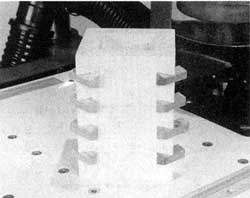
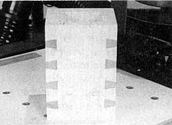
Beyond the basic joints, under-table routing provides the ability to form two very unique joints that would be difficult (if not almost impossible) to form with any other machine. These joints are the false dovetail and the false finger-lap.
Both of these joints are formed by gluing your project together, cutting grooves for contrasting wood “keys” in the corners and gluing the keys into position. Once completed, the corners of your project have the look of dovetails or finger-lap joints.
To cut these unique joints, begin by building a false dovetail fixture like the one shown in Figure 22-54. Note that the dimensions for this fixture are based on 1/2″ dovetails spaced 1″ apart. If your dovetails will be larger, smaller, and/or spaced differently, you will have to adjust your fixture accordingly.
Before you can cut the dovetail slots (or square slots, if you’re making finger-lap joints), you must first assemble your project with 45° mitered corners and glue it together. Warning: Clamp and let glued-up stock dry for at least 24 hours prior to routing.
After the glue has dried, begin by positioning your project in the fixture with its side against the spacer bar. Turn on the router. Move the miter gauge (with fixture attached and project in position) into the bit to make the first cut (Figure 22-55). Turn off the router.
Return the miter gauge to its starting position. Move the project to the right in the fixture and drop the slot you just cut over the spacer bar (Figure 22-56). Move the miter gauge into the bit again to make the second cut. Repeat the above procedure for all subsequent slots on each corner of your project (Figure 22-57).
Next, make the dovetail “keys” that will slip into the grooves you’ve cut. Begin by choosing a piece of contrasting stock, approximately 3/4″ thick x 3″ wide.
Set up the hold-down fences (Figure 22-16) and feather boards, and adjust the bit’s depth-of-cut equal to the depth you cut in your project. Begin by making the first pass on one side of your key stock (Figure 22-58). Now, flip the stock over and make the second pass on the other side (Figure 22-59).
Check to see if the key fits into the slot you’ve cut in the corners of your project. If it’s too snug, adjust your fence to make a slightly deeper cut in your key stock (which will create a narrower key). Keep working with this until the key fits snugly in the slots you have cut.
Next, saw the full-length keys off your key stock, and discard the scrap in the center. Then, cut the keys to about 1″ to 1-1/4″ long.
Spread glue on each side of the keys and insert them into the slots in the corners of your project (Figure 22-60). After they have dried, sand the keys flush with the project (Figure 22-61).
This same process will work for finger-lap joints. Instead of using a dovetail cutter, use a straight 1/4″, 3/8″ or 1/2″ un-piloted bit.