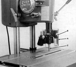
The drill press mode of the Mark V can be used as a stationary router in both its vertical and horizontal positions. But to accomplish this, a special chuck is required to secure the high-speed bits because of the side thrust that is characteristic of routing operations. The chuck is locked firmly in place by securing its setscrew against the main spindle’s tapered flat. Two setscrews lock the bits in the chuck. Router bits can be straight or, like the dovetail cutter, may have shaped cutting edges. The routing accessories are shown in Figure 10-1.
Routing cuts are made at high speed and with reasonable feed pressure so the bit can do its job without choking or burning. Always perform routing operations at “Fast” speed. Do not form excessively deep cuts in a single pass. Deep cuts are easier to make and the results will be smoother if you get to full depth of cut by making repeat passes no deeper than 1/4″ or less, depending on the size of the bit.
Routing Safety
Warning: Before using the routing accessory, read and understand these Important safety instructions:
Danger Zone-The danger zone on the Mark V when routing extends 3″ all around the bit and chuck and 5″ in front of the bit. Always keep your fingers and hands out of the danger zone.
When you work at the router, pay attention to where you put your hands. Be certain they aren’t in front of the bit when you advance the quill. Never reach in toward or in front of the bit to clear away scraps. Turn off the machine and let it come to a complete stop first.
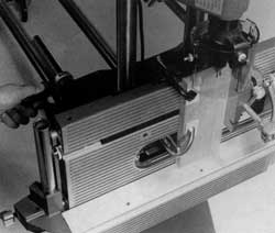
Guard for the Router-The circular shield and brush assembly must always be used for router operations. It mounts to the quill and is adjustable to accommodate various thickness’ of stock.
- Wear proper eye and ear protection.
- Tuck long hair under a hat or tie It up. Do not wear ties, gloves, jewelry or loose clothing. Roll sleeves up above your elbows. Wear non-slip footwear.
- Always mount the circular shield and brush assembly on the Mark V quill before performing routing operations.
- Always run the router at ‘FAST’ speed.
- Avoid taking deep cuts. With the exception of single-pass dovetail cuts, limit depth of cut to 1/4″ for each pass when using bits up to 1/2″ diameter. When using bits over 1/2″ diameter, limit depth of cut to 1/8″.
- Never freehand rout. Always use the rip fence or miter gauge when using bits without pilots, and a starter pin when using bits with pilots.
- Always feed the workpiece against the rotation of the bit. Otherwise a kickback will occur.
- Feed the workpiece slowly. Use extra care when routing stock that contains figured grain or knots, as these may cause kickbacks.
- Use a push stick to feed a narrow workpiece. When it Is necessary to push a workpiece underneath the shield, use a long piece of scrap wood.
- Cut with the grain when straight-line routing.
- Do not stand directly inline with the workpiece. In the event of a kickback you could be hit.
- When routing across the grain of workpieces up to 10″ wide, always use your miter gauge with safety grip to control the workpiece.
- When stop routing, always use stop block(s) to control the length of cut. Failure to use stop block(s) will cause a kickback.
- When routing an oversize workpiece, always use at least one push block to help control the workpiece. Hold the workpiece firmly against the rip fence.
- When edge routing with a piloted bit, always use either a starter pin or a fence to start the cut and/or guide the workpiece.
- Set speed to ‘SLOW,’ turn off and unplug the Mark V before mounting router bits.
- Make sure the setscrew in the chuck is tightened against the fiat of the main spindle and the bit is secured tightly in the chuck. Then remove the Allen wrench immediately.
- Listen for chatter or signs of looseness at startup. If you hear, see or suspect problems, turn off and unplug the machine. Correct any problem before proceeding.
- Keep the bits clean, maintained and sharp.
Router Bits
Router bits come in a variety of shapes and sizes, each designed to perform a specific operation. You’ll also find how to use decorative edging bits and how to perform additional routing operations.
General Routing
When routing, the distance from the outer edge of the workpiece to the bit determines the setup:
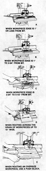
- When workpiece edge is 1″ or less from bit, use one feather board on the infeed side and an additional feather board on the outfeed side, both secured in the table slot. Use a push stick, or when it’s necessary to push work-piece underneath the shield, use a piece of wood (Figure 10-2A).
- When workpiece edge is 1″ to 2-3/4″ from bit, use two feather boards as above or use one feather board centered to the bit, secured in table slot. Use a push stick or piece of wood to push the workpiece under the shield (Figure 10-2B).
- When workpiece edge is 2-3/4″ to 5-1/2″ from bit, use one feather board centered to the bit and secured to table with two C-clamps. Use a push block (Figure 10-2C).
- When routing across the grain of workpieces up to 10″ wide, use the miter gauge and safety grip. Workpiece must extend 5-1/2″ away from bit (Figure 10-2D).
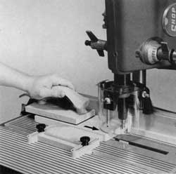
- When routing an oversize workpiece, use a push block (Figure 10-2E).
Router cuts made with the grain are smoother than cross grain or against the grain cuts, but you can’t always work that way. When you can’t, work with a slower feed rate and less depth of cut for optimum results.
- The depth of single pass cuts should be limited as follows:
- 1/4″ maximum depth of cut for bits up to 1/2″ diameter.
- 1/8″ maximum depth of cut for bits over 1/2″ diameter.
- Less than the above limits when routing extremely hard wood.
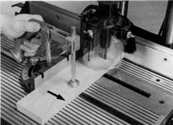
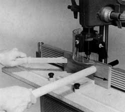
Feed the workpiece from left to right against the bit’s direction of rotation (Figure 10-3). The action of the properly installed bit will help keep the workpiece against the fence.
When using auxiliary facings, it is a good idea to remember that when the fence is behind the bit, the pass is also made from left to right.
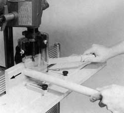
Make cross grain cuts by working with the miter gauge and safety grip (Figure 10-4). Some chipping will occur where the bit breaks through, so allow for it by making the cut on an extra-wide piece. Then you can remove the chipped edge using the table saw or jointer.
Stock edges are often routed to form rabbets. For this and similar kinds of work, make an auxiliary facing, as shown in Figure 10-5, that can be attached to the rip fence as shown in Figure 10-6. The relief area allows adjustments so the bit can project beyond the bearing surface of the facing. The depth of cut is controlled by quill extension; width of cut is controlled by how much the bit projects. If you need a wider cut, move the table or reposition the fence and make another pass.
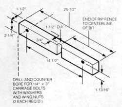
Figure 10-5. Construction details of the auxiliary facing.
Mortises
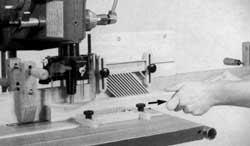
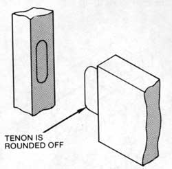
Mortises with round ends can be formed with a router bit (Figure 10-7). Mark the stock where the mortise begins; clamp stop blocks to a fence extension to control the length of the mortise in both directions. Position the workpiece against the left stop block so the bit will be at the first mark, extend the quill to penetrate the workpiece, and lock it. Then move the workpiece until it contacts the right stop block. Mortise cuts are usually quite deep, so repeat passes will be necessary. The width of the mortise depends on the size of the bit.Mortises formed this way will have round ends; therefore, the tenon must be shaped to fit (Figure 10-8).
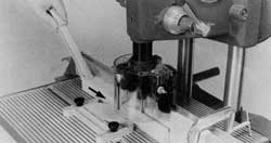
Slots-Slots are formed the same way as mortises except that after the quill is extended and locked in position, the cut starts at the end of the workpiece and continues until it contacts the stop block (Figure 10-9).
Dovetails
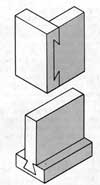
A dovetail is one of the strongest joints in woodworking because it will resist a pulling strain in every direction but the one from which the tenons are inserted into the slots. Two common applications are shown in Figure 10-10.
The same dovetail cutter is used to form both the tenon and the slot. Mating the parts is a matter of positioning the cuts in proper relationship to each other.
Spacing of the cuts is determined by the size of the cutter and the design of the joint. One method is to mark the workpiece and align each cut with the cutter. Another method is to pencil mark the worktable so that the edge of the workpiece can be moved forward to a new mark after each cut. When you mark the worktable, first determine the centerline of the spindle; then mark the cutlines by measuring toward the worktable edges, front and rear. One technique is to use measuring tape which has a gummed side. This may be placed on the worktable and then removed when not in use.
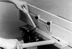
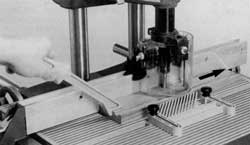
To cut dovetail tenons as shown in Figure 10-11, position the worktable parallel to the way tubes. Use the table height lever (Model 500) or table height crank (Model 510) as a forward feed mechanism, the stop collars from the lathe tailstock to control table movement, the quill feed lever to obtain exact depth of cut, the rip fence as a platform for the workpiece and the miter gauge to square the work-piece to the cutter. When feeding the workpiece forward against the cutter, move the worktable slowly, and be sure the workpiece is clamped securely in place. After the cut is made, turn off the Mark V and return the worktable to the starting position. If desired, place the workpiece for the next cut and repeat the procedure.
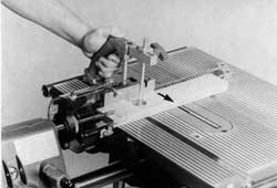
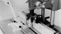
The mating cuts are formed with the worktable in the horizontal position and with the fence used as a guide (Figure 10-12). The table is brought up as close to the cutter as possible, and the final adjustment is made by extending the quill. The workpiece is fed forward against the cutter. A stop is clamped on the fence to control the length of cut. For spacing, the fence can be moved for each new cut or the worktable can be advanced-again by using the table height mechanism as a forward feed device. When feeding the workpiece against the cutter, hold it firmly on the worktable and push it slowly. Caution: If the cut is for a through dovetail, use a scrap block between the work and the table.
The tenon on a single, wide dovetail is formed by making two cuts, one on each end of the stock. The mating part is formed the same way, with the waste stock cut away by running the work across the cutter within limits set by the two end cuts and stop blocks. Care must be exercised in positioning the pieces for successive cuts, but testing in scrap wood before cutting will make this easier. By using the setups shown in Figures 10-13 and 10-14, you can join boards edge-to-edge or provide a sliding arrangement.
Cut the slot in one pass by placing the table as shown and adjusting it so the cut is made directly down the centerline of the board (Figure 10-13). Depth of cut is set by lowering the quill and locking it in position. Feed the workpiece slowly and keep it flat against the table. Don’t force the workpiece. The tenon requires two passes. The workpiece is positioned so the cutter forms the tenon on one side of the board. Then the workpiece is turned and the second pass is made; thus, the cutter completes the forming of the tenon on the opposite surface of the board (Figure 10-14). Here, even more than elsewhere, be sure the workpiece is held firmly and flat against the table.
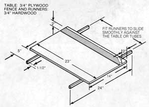
Wide stock that must be grooved across the grain requires a sliding table arrangement to which the work can be clamped (Figure 10-15). The fixture is constructed as shown in Figure 10-16, with the runners situated so the platform will slide smoothly on the table. The table is raised to an approximate position and the final adjustment for depth of cut is made by using the quill feed lever.
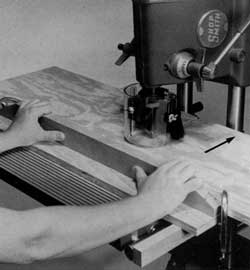
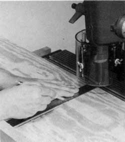
With this arrangement the length of cut is limited to the distance from the cutter to the tubes. On narrow stock the groove can be completed in one pass by using a spacer board between the workpiece and the fence. Wide boards require two cuts from opposite sides of the board on a common centerline. Alignment is important. Locate the cutter center by marking a pencil line on the fence of the sliding table. Mark lines on the workpiece to locate the centerlines of the grooves. Align these with the mark on the fence. Since the first half-cut (on wide boards) removes the line, it is necessary to use a straightedge to realign the workpiece with the mark on the fence before completing the cut (Figure 10-17). This method is not limited to dovetail grooves; straight grooves are cut with router bits, and the procedure is exactly the same.
Horizontal Routing
As shown in Figure 10-18, grooves are cut with the Mark V in the horizontal position. A fence extension and feather board provide guidance and support as the workpiece is fed through. The depth of cuts given in “General Routing” apply. If it’s tough to feed the workpiece, the workpiece chatters, or the cut is rough, you are probably cutting too deep. Back off and make repeat passes instead. The same setup can be used to form rabbets or tongues.
Handle cross grain cuts by working with the miter gauge and using the miter gauge stop rod to determine the depth of cut (Figure 10-19). There will be some feathering at the end of the cut, so work on a piece that is wider than you need. Remove the chip by making a light jointer cut or by sawing.