Sharpening (grinding and honing) woodworking tools is very personal and can be accomplished in many ways–you will sharpen tools the way that works best for you. Tools are ground on machines and then honed on several types of stones. Grinding eliminates defects in the cutting edge by removing metal from the tool. Honing puts a razor sharp edge on the ground cutting edge of the tool. This chapter will cover the different ways of grinding and honing many of the basic cutting tools used for woodworking. Because of the diverse nature of woodworking and the thousands of tools available we can not possibly cover everything in just one chapter. For additional sharpening information consult the tool manufacturer or your local library.
Grinding Machines And Accessories
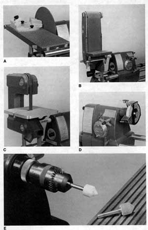
The Shopsmith machines and accessories that we will be using to show the different grinding techniques are the Disc Sander, Belt Sander, Strip Sander, Grinding Wheel, Sharpening Guide, plus specialty grinding stones (Figure 24-1). The abrasives generally used to perform grinding tasks are: aluminum oxide and silicon carbide for belts and discs used on power sanders, and silicon carbide for wheels used in power grinders.
Sharpening Safety
As with other power tool operations, sharpening safety is Paramount! Know the machine that you are about to use. To protect yourself and others from personal injury take the time to review these important safety considerations:
Read, understand, and follow ALL the safety and other information in the Owners Manual that applies to the machine, machines or accessories you plan to use.
- Always wear proper eye and face protection.
- Always support the tool that you are grinding.
- Always operate the machine at the recommended speed.
- Never turn on the machine with the tool or cutter already against the abrasive.
- Never connect a dust collection system to the grinding machine or accessory during grinding operations. Sparks and/ or hot pieces of metal could ignite the sawdust or debris in the collection bag.
- Never perform any grinding operations without the appropriate shields and guards in place and properly positioned.
- Always inspect the abrasive surface of the disc, belt, or wheel for any wrinkles, tears or cracks. Replace any defective abrasive materials IMMEDIATELY. Always grind with the tool’s cutting edge pointing AWAY from the direction of rotation of the disc, belt or rubber bonded abrasive wheel.
- Never mount the Velcro Sanding System on the disc sander for grinding operations. The cutting edge of the tool or cutter will dig into the soft-backed sandpaper and throw the tool or cutter from your hands possibly causing injury and certainly damaging the tool and the sanding system.
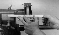
Grinding Lathe Chisels
Lathe chisels can be ground on several Shopsmith machines. However using the Shopsmith Sharpening Guide with the disc sander, the belt sander or the strip sander is probably the easiest. Chisels can also be ground on the grinding wheel accessory but there is less apparatus to guide the chisels so accuracy is more difficult. Lathe chisels are held three different ways for scraping, cutting, and shearing. Therefore, they must be ground properly for the way they are going to be used. Some chisels can be ground and held to cut in more than one way while others are designed to cut stock one way only.
The skew and the gouge are generally ground for shearing with a long bevel and then honed to a razor sharp edge. They are intended to shear or cut (depending on how they are held) and are used to make spindle turnings. They can, however, also be ground and used as scraping tools.
The parting tool is ground for either cutting or scraping and is honed razor sharp only when it is intended for cutting. The roundnose chisel is generally ground with a short bevel and the burr is left on the cutting edge. This chisel is seldom honed and is intended to scrape. It is used to make both spindle and faceplate turnings.
Shearing chisels can be used to scrape and scraping chisels can be used to shear if this works best for you, but there are a few things to remember.
Warning: When any chisel ground to a shearing angle is used to remove stock with a scraping technique, especially with alternating grain direction, the sharp cutting edge will dig into the stock, stalling the machine or throwing the chisel and! or the stock. This will leave a deep gouge in the stockand possibly throw the tool from your hands causing injury and certainly damaging the tool.
Round bottom gouges, even when ground for scraping, will roll when the upper corners come in contact with the rotating stock causing them to dig into the stock. This will throw the tool from your hands possibly causing injury and certainly damaging the tool and the workpiece.
The double beveled chisels, skew and parting tool, are measured across both bevels. This is known as an included angle. (This angle includes both bevel angles.)
The longer the bevel or the smaller the angle ground on the chisel, means a sharper tool that will leave a smoother cut. However, the tool will be more difficult to control.
As you grind away metal, the chisel will become short and the handle ferrules will hit the sharpening guide, especially at the shearing settings. By then you will have ground past the heat treated end. For this reason, the chisel dulls quickly and needs to be replaced.
When you’re using the disc sander or the belt sander mounted on the Mark V, always grind at “Slow” speed. For grinding on the strip sander, follow the recommended speeds for the different grits in the Owners Manual.
Because grinding removes metal with a moving abrasive working against a stationary metal tool, a great deal of frictional heat is created. To keep this heat from building up and destroying the factory heat treating and hardening of the tool (temper), hold the tool against the abrasive momentarily then slide it away. Repeat this procedure until the tool has been sufficiently ground. Caution: Have a container of water nearby to cool (quench) the tool if it becomes too hot to touch. If you notice that the too/is discoloring and turning blue, you are either holding the tool against the abrasive too long or too hard, the abrasive is dull or the speed setting is too fast.
When you’re using the disc sander, the dust chute is used to contain the abrasive particles and protect the way tubes from grit. An alternative to using the dust chute is to place an 8″ to 12″ wide piece of scrap lumber on the way tubes under the sanding disc. Caution: When you’re finished grinding, always slide the power plant away from the grinding position and wipe the way tubes clean.
Grinding Lathe Chisels using the Sharpening Guide
The Shopsmith Sharpening Guide mounts on the disc sander, belt sander and the strip sander and is used to grind skews, gouges, parting tools and roundnose chisels. Set up the machine you will be using and grind the chisels accord-ing to the applicable instructions below. To determine the sharpening guide angle settings, refer to Table 24-1.
| Table 24-1: Sharpening Guide Angle Settings | |||||||||
| Left Setting (Shearing) | Right Setting (Scraping) | ||||||||
| 20 | 15 | 10 | 5 | 0 | 5 | 10 | 15 | 20 | |
| Skew | 25 | 30 | 35 | 40 | 45 | 50 | 55 | 60 | 65 |
| Gouge | 25 | 30 | 35 | 40 | 45 | 50 | 55 | 60 | 65 |
| Parting Tool | 40 | 45 | 50 | 55 | 60 | 65 | 70 | 75 | 80 |
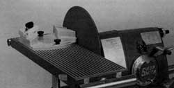
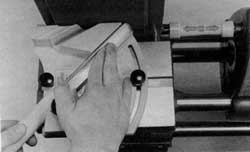
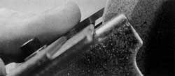
Disc Sander Setup-Mount the sharpening guide on the Mark V extension table (Figure 24-6). Warning: To sharpen lathe chisels, mount the sharpening guide to the extension table only. Mounting the guide to the worktable may cause the cutting edge of the chisel to dig into the abrasive and the tool to be thrown from your hands.
Adjust the sharpening guide to the desired angle setting. Slide the sanding disc to within 1/16″ of the sharpening guide then secure the power plant lock. Warning: Never use the Velcro Sanding System to grind tools.
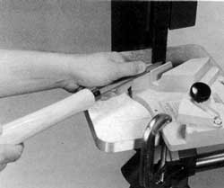
Belt Sander Setup-Position the belt sander vertically and set the table to the “0” setting. Position the parting tool station of the sharpening guide in front of the belt sander backup plate. Adjust the guide to the desired angle setting. Warning: Position the sharpening guide to within 1/16″ of the belt and secure the table locking setscrews (Figure 24-7).
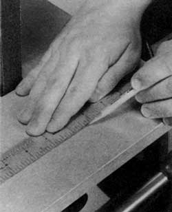
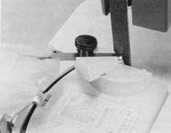
Strip Sander Setup-Set the strip sander worktable to 90° and adjust the sharpening guide to the desired angle setting. Because there are no table slots or mounting holes in the strip sander table, the sharpening guide must be clamped to the table top. An index line is used to align the guide. Draw this line 3-5/8″ from, and parallel to the platen (Figure 24-8).
When setting the angle, position the hole in the rear of the sharpening guide and the angle setting indicator directly over the index line. Slide the sharpening guide along the line until the desired station is in front of the belt. Make sure the sharpening guide is within 1/16″ of the belt, then clamp the guide securely to the table (Figure 24-9).
Grinding the Skew-The skew chisel has a bevel ground on both sides at an angle not perpendicular to either the side faces or the top and bottom edges. To grind this compound angle the skew must be held at an angle to the abrasive and leaned to the left and to the right. These angles are controlled by the sharpening guide.
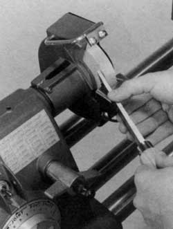
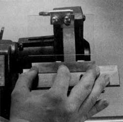
Position the tip of the skew down and the side against the left wall of the second station of the sharpening guide (Figure 24-10). Be sure the skew is not touching the abrasive and the speed dial is set to “Slow” (if you are using the Mark V), then turn on the machine.
Gently slide the skew against the wall of the skew grinding station and into the moving abrasive. Hold the chisel there momentarily then back it away. Repeat this several times.
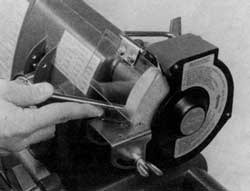
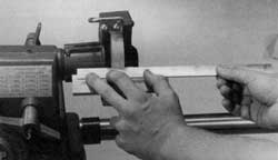
Turn the skew over and position the tip of the skew up and lay the side of the skew against the right wall of the second station (Figure 24-11).
Gently slide the skew against the station and into the moving abrasive. Hold it there momentarily then back it away. Repeat this several times.
Grind away only enough metal to remove any damage to the cutting edge and create a slight burr. If the skew is being ground for scraping, then it is ready to use (the burr is sharp and scrapes very well). If the skew is being ground for shearing or cutting, it will need to be honed to a razor sharp edge.
Grinding the Gouge-The gouge chisel has a bevel ground on the convex side (bottom) at an angle measured from the concave side (top). This bevel is curved to form a rounded cutting edge. To grind this complex curved bevel, the gouge must be held at the proper angle, fed into the abrasive and rotated. The angle is controlled by the sharpening guide.
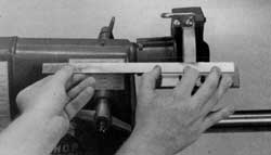
Place the gouge in the third station of the sharpening guide and lay the side of the gouge against the left wall of the station (Figure 24-12). Rotate the gouge until its center touches the abrasive.
With the machine “OFF” prac-tice rotating the gouge, first clockwise from the center to the edge, and then counterclockwise from the center of the gouge to the edge.You should notice while rotating the gouge that in order to keep the bevel in contact with the abrasive, you must slide the gouge forward on the station as the bevel is ground from the center to each edge.
After you get the feel of this grinding motion, be sure the gouge is not touching the abrasive and the speed dial is set to “Slow” (if you are using the Mark V), then turn on the machine.
Gently slide the gouge against the wall of the station and into the moving abrasive. Start rotating the gouge, like you practiced. Repeat this several times.
Grind away only enough metal to remove any damage to the cut-ting edge and create a slight burr. If the gouge is being ground for scraping, it is ready to use (the burr is sharp and scrapes very well). If the gouge is being ground for shearing or cutting, it will need to be honed to a razor sharp edge.
Grinding the Parting Tool– The parting tool has a bevel ground on both the top and bottom edges. To grind these angles the parting tool must be held on its side at the proper angle to the moving abrasive, turned over and reset at the exact same angle. These angles are controlled by the sharpening guide.
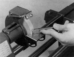
To grind the parting tool, lay the side of the parting tool in the first station of the sharpening guide (Figure 24-13). Be sure the parting tool Is not touching the abrasive and the speed dial is set to “Slow” (if you are using the Mark V), then turn on the machine.
Gently slide the parting tool on the station and into the moving abrasive. Hold it there momentarily then back it away. Repeat this several times.
Turn the parting tool over and lay the other side in the first station. Slide the parting tool on the station and into the moving abrasive. Hold it there momentarily then back it away. Repeat this several times. Grind away only enough metal to remove any damage to the cutting edge and create a slight burr. It is VERY important to grind an equal amount from each bevel so that the widest part of the parting tool is exactly at the cutting edge. If the parting tool is being ground for scraping, then it is ready to use (the burr is sharp and scrapes very well). If the parting tool is being ground for cutting, it will need to be honed to a razor sharp edge.
Grinding the Roundnose Chisel-The roundnose chisel has a bevel ground on the bottom at an angle measured from the top. This bevel is curved to form a round cutting edge. To grind this curved bevel the roundnose chisel must be held at the proper angle to the moving abrasive, pivoted and fed into the abrasive. The bevel angle is controlled by the sharpening guide.
Grinding the roundnose chisel on the fourth station is the only grinding operation that does not repeat the “factory” angle. The new 15° bevel angle is ideal for scraping. The distance between the pivoting station and the moving abrasive will set the radius of the cutting edge. Position the pivoting station close to the abrasive and the cutting edge will be ground completely around the chisel leaving no sharp corners. Position the pivoting station further away from the abrasive and the cutting edge will be ground around the chisel on a large radius leaving sharp corners where the sides and the curved cutting edge join.
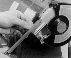
To grind the roundnose chisel, position it, bevel up in the fourth station (the pivoting station). Slide it under the knob until the center of the round nose chisel touches the abrasive and tighten the knob (Figure 24-14).
With the machine “OFF” practice pivoting the roundnose chisel first to the left, and then to the right to complete the edge. You will notice that the chisel will need to be repositioned further forward on the grinding station to complete the bevel. After you get the feel of this grinding motion, be sure the round-nose chisel is not touching the abrasive and the speed dial is set to “Slow” (if you are using the Mark V), then turn on the machine.
Gently slide the roundnose chisel in the fourth station until it just touches the moving abrasive. Tighten the knob and start pivoting the roundnose chisel, like you practiced. Repeat this several times.
Grind away only enough metal to remove any damage to the cutting edge and create a slight burr. The roundnose chisel is ground for scraping, so it is ready to use as is and should not be honed (the burr is sharp and scrapes very well).
Grinding Lathe Chisels using the Grinding Wheel
The Shopsmith Grinding wheel mounts on the Mark V and will grind skews, gouges, parting tools and roundnose chisels. Set up the grinding wheel on the Mark V and grind the chisels according to the applicable instructions below.
Grinding the Skew-The skew chisel has a bevel ground on both sides at an angle not perpendicular to either the side faces or the top and bottom edges. To grind this compound angle the skew must be held at the proper angle to the side of the wheel and leaned to either the left or to the right on the appropriate sides of the wheel. Warning: Do not grind the skew on the front of the wheel. This will leave a hollow ground bevel on the skew that may make the chisel difficult to control.
One angle is controlled by the tool rest and the other angle (the lean of the tool) is controlled by feel.
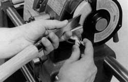
To find the desired tool rest angle setting hold the skew on the tool rest with the tip up and the bevel of the cutting edge against either side of the wheel. Loosen the wing nut and pivot the tool rest until the cutting edge is parallel to the rotation of the wheel (Figure 24-15). At the same time, slide the tool rest to within 1/16″ of the wheel and then secure the wing nut.
To grind the skew, position the tip up and lay the right side bevel against the left side of the grinding wheel (Figure 24-16).
Tilt the skew away from the wheel and be sure the skew is not touching it and the speed dial is set to “Slow”. Then turn on the Mark V and set the speed dial to “R” (3400 RPM).
Gently lean the skew back toward the side of the grinding wheel. Feel for the bevel of the skew against the side of the grinding wheel. Hold it there momentarily then lean it away. Repeat this several times.
Reposition the left bevel with the tip up near the right side of the wheel (Figure 24-17).

Gently lean the skew into the side of the grinding wheel. Feel for the bevel of the skew against the side of the grinding wheel. Hold it there momentarily then lean it away. Repeat this several times.
Grind away only enough metal to remove any damage to the cutting edge and create a slight burr. If the skew is being ground for scraping, then it is ready to use (the burr is sharp and scrapes very well). If the skew is being ground for shearing or cutting, it will need to be honed to a razor sharp edge.
Grinding the Gouge-The gouge chisel has a bevel ground on the convex side (bottom) at an 293 angle measured from the concave side (top). This bevel is curved to form a rounded cutting edge. To grind this complex curved bevel, the gouge must be held at the proper angle to the grinding wheel, rotated and fed into the wheel. The angle and the roll of the gouge is controlled by feel.
Set the tool rest to 90° and slide it to within 1/16″ of the wheel and then secure the wing nut. Set the gouge on the tool rest with the cen-ter of the bevel against the front of the grinding wheel and the handle pointing to the left.
Practice rolling the gouge toward the front of the tool rest (Figure 24-18). Feel for the bevel against the grinding wheel while keeping the side firmly against the tool rest. Repeat this movement with the gouge handle pointing to the right (Figure 24-19).
When you feel confident with the rolling movement of the gouge, slide it away from the wheel. Be sure that the gouge is not touching the wheel and that the speed dial is set to “Slow”. Then turn on the Mark V and set the speed dial to “R” (3400 RPM).
Gently slide the gouge into the grinding wheel. Feel for the bevel of the gouge against the grinding wheel. Roll the gouge just as you practiced, first with the handle to 294 the right, then with the handle to the left. Repeat this several times.
Grind away only enough metal to remove any damage to the cutting edge and create a slight burr. If the gouge is being ground for scraping, then it is ready to use (the burr is sharp and scrapes very well). If the gouge is being ground for shearing or cutting, then it will need to be honed to a razor sharp edge.
Grinding the Parting Tool– The parting tool has a bevel ground on both the top and bottom edges. To grind these angles the parting tool must be held on its edge at the proper angle to the grinding wheel, turned over and held at the exact same angle. Adjust the tool rest to match the center of the bevel previously ground on the parting tool and slide the tool rest to within 1/16″ of the wheel and then secure the wing nut.
Lay the edge of the parting tool on the tool rest (Figure 24-20). Practice sliding the tool forward while holding it perpendicular to the tool rest and the grinding wheel. Try this on both sides of the parting tool.
When you feel confident with the movement of the parting tool, slide it away from the wheel. Be sure that the parting tool is not touching the wheel and that the speed dial is set to “Slow”. Turn on the Mark V and set the speed dial to “R” (3400 RPM).
Gently slide the parting tool on the tool rest and into the grinding wheel. Hold it there momentarily then back it away. Repeat this several times.
Turn the parting tool over and lay the other edge on the tool rest. Slide the parting tool on the tool rest and into the grinding wheel. Hold it there momentarily then back it away. Repeat this several times.
Grind away only enough metal to remove any damage to the cutting edge and create a slight burr. Be sure to grind an equal amount from each side so that the widest part of the parting tool is exactly at the cutting edge. If the parting tool is being ground for scraping, then it is ready to use (the burr Is sharp and scrapes very well). If the parting tool is being ground for cutting, itwill need to be honed toa razor sharp edge.
Grinding the Roundnose Chisel-The roundnose chisel has a bevel ground on the bottom at an angle measured from the top. This bevel is curved to form a rounded cutting edge. To grind this curved bevel the roundnose chisel must be held at the proper angle to the grinding wheel, pivoted and fed into the wheel. The bevel angle is controlled by the tool rest.
Grinding the Roundnose Chisel-The roundnose chisel has a bevel ground on the bottom at an angle measured from the top. This bevel is curved to form a rounded cutting edge. To grind this curved bevel the roundnose chisel must be held at the proper angle to the grinding wheel, pivoted and fed into the wheel. The bevel angle is controlled by the tool rest.
Set the tool rest to a 5° to 10° angle to the wheel and slide the tool rest to within 1/16″ of the wheel. Then secure the wing nut.
Grinding the roundnose chisel is the only grinding operation that does not repeat the “factory” angle. The hollow-ground 50 to 10° bevel angle is excellent for scraping. Set the roundnose chisel, bevel down on the tool rest. Slide the chisel forward until the center of the chisel touches the grinding wheel (Figure 24-21).
With the machine “OFF” practice pivoting the roundnose chisel first to the left, and then to the right to complete the edge. After you get the feel of this grinding motion, be sure the roundnose chisel is not toucriing the wneel and that the speed dial is set to “Slow”. Turn on the Mark V and set the speed dial to “R” (3400 RPM).
Gently slide the roundnose chisel on the tool rest and into the grinding wheel. Like you practiced, pivot the chisel to grind the bevel.
Grind away only enough metal to remove any damage to the cutting edge and create a slight burr. The roundnose chisel is ground for scraping, so it is ready to use as is and should not be honed (the burr is sharp and scrapes very well).
Honing Lathe Chisels
After the skews, gouges, and parting tools are ground for either shearing or cutting, their cutting edges must be honed razor sharp.
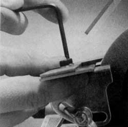
In order to hone the chisel you must be able to find and recognize the burr created by grinding. This must be done properly and with extreme care to avoid cutting yourself. As you progress from coarser to finer stones, the burr will become smaller and more difficult to find, but after you become more practiced at honing this will become second nature.
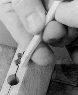
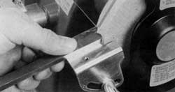
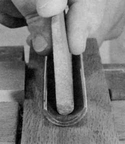
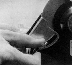
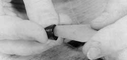
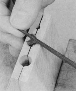
To find the burr, lightly rub your finger at right angles to the cutting edge from the back of the bevel toward the cutting edge and across it (Figure 24-22). Warning: Be careful not to slide your finger along the cutting edge. Even though the chisel is not yet honed, the burr is sharp.
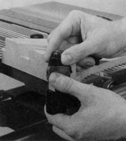
Start honing with a coarse stone. Apply a generous amount of liquid (if required) to the surface of the stone. Set the chisel in the center of the hone, and rock the chisel on the bevel until you see the liquid squeeze out from between the ground surface and the stone. This helps to show that you’re holding the chisel at the proper angle. Repeat this until you easily feel the bevel seat flat on the stone. Slide the chisel over the hone as directed for each class of hone.
By repeating this procedure on progressively finer stones you will be able to hone the cutting edge of the chisel razor sharp.
There are a couple of tests to check the “sharpness” of the cutting edge: (1) A razor sharp cutting edge will cut end grain of wood with little effort. (2) A razor sharp cutting edge will seem to drag rather than slip when pulled across the corner of a piece of hardwood. Do not use paper to test the sharpness because the glues in the paper will dull the edge you worked so hard to obtain.
Honing the Skew
The skew is honed much like a pocket knife. Each has a bevel ground on both sides of their cutting edge. The skew must be honed on the two bevels. This will remove the grinding burr and sharpen the cutting edge. By repeating this procedure on progressively finer stones you will be able to hone the cutting edge razor sharp.
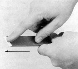
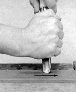
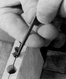
Using Oil Stones and Diamond Hones–Hold one bevel of the skew on the hone. Slide the skew over the hone with the cutting edge pointing in the same direction you are sliding the skew (Figure 24-23). Think of it as trying to shave off a thin sliver of the hone. Turn the skew over and repeat the procedure to hone the other bevel.
Using Water Stones and Rubber Bonded Abrasives–To hone skews with a cutting edge wider than 1/2″ follow the oil stones and diamond hones instructions.
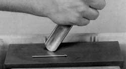
For skews with narrower cutting edges, slide the skew over the hone with the cutting edge pointing away from the direction you are sliding the skew (Figure 24-24). Think of it as trying to smooth over the surface of the hone. Turn the skew over and repeat the procedure to hone the other bevel.
Honing the Gouge
The gouge must be honed on both the bevel ground on the outside and the concave inside. This will remove the grinding burr and sharpen the cutting edge.
A gouge slip or other rounded (convex) slip will be needed to hone the inside (concave) of the gouge. This medium or fine slip should match the profile of the gouge as close as possible.
Using Oil Stones and Diamond Hones–Hold the bevel of the gouge on the hone. Roll the gouge as you push it over the hone. The cutting edge should be pointing in the same direction you are pushing the gouge (Figure 24-25). Think of it as trying to shave off a thin sliver of the hone as you roll the gouge.
Change to the slip. Apply a generous amount of oil to the inside of the gouge. Set the hone in the gouge. Slide the slip from the cutting edge to the handle while rotating the gouge so the entire cutting edge on the inside is honed (Figure 24-26). Then return to the flat bench hone.
Using Water Stones and Rubber Bonded Abrasives–Hold the bevel of the gouge on the hone. Roll the gouge as you pull it over the hone. Slide the gouge over the hone with the cutting edge pointing away from the direction you are sliding the gouge (Figure 24-27). Think of it as trying to smooth over the surface of the hone as you roll the gouge.
Change to the water slip hone. Apply a generous amount of water to the top surface of the hone. Set the concave side of the gouge down on the slip. Slide the gouge away from the slip while rotating the gouge so the entire cutting edge is honed on the inside. Then return to the flat bench hone.
Honing the Parting Tool
The parting tool is honed on the bevel ground on both sides of the cutting edge. This will remove the grinding burr and sharpen the cutting edge.
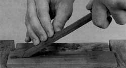
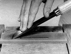
Using Oil Stones and Diamond Hones–Hold the bevel of the parting tool on the hone. Slide the parting tool over the hone with the cutting edge pointing in the same direction you are sliding the tool (Figure 24-28). Think of it as trying to shave off a thin sliver of the hone. Turn the parting tool over and repeat this on the other bevel.
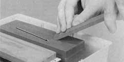
Figure 24-29. Point the cutting edge away from the direction you are sliding the tool.
Using Water Stones and Rubber Bonded Abrasives–Hold one bevel of the parting tool on the hone. Slide the tool over the hone with the cutting edge pointing away from the direction you are sliding the tool (Figure 24-29). Think of it as trying to smooth over the surface of the hone. Turn the parting tool over and repeat the procedure to hone the other bevel. Warning: Never attempt to hone the parting tool with the rubber bonded abrasive wheel mounted on the grinding wheel accessory. The cutting edge of the parting tool will dig into the soft abrasive and throw the tool from your hands, possibly causing injury and certainly damaging the tool and the rubber bonded abrasive wheel.
Sharpening Bench Chisels
A bench chisel may be one of the most used and most abused tools in the shop. Along with chiseling, it’s sometimes used as a pry tool, a wedge, or even a substitute for a screwdriver. Because of this, the bench chisel could be the most sharpened tool in the shop. To sharpen bench chisels, they must be ground, then honed.
Grinding Bench Chisels using the Sharpening Guide
The Shopsmith Sharpening Guide mounts on the disc sander, belt sander and the strip sander and is used to grind bench chisels. Set up the machine you will be using and grind the chisels according to the applicable instructions below. To determine the sharpening guide angle settings, refer to Table 24-1.
Disc Sander Setup–Mount the sharpening guide on the Mark V worktable and adjust the worktable height. Mount the sharpening guide to the worktable only. Mounting the guide to the extension table will not allow the required 9° table tilt.
Tilt the worktable 9° toward the abrasive. To adjust the sharpening guide to the desired angle setting, lay the flat bottom of the bench chisel against the right-hand wall of the second station. With the tip of the chisel against the abrasive, pivot the sharpening guide until the bevel of the chisel sets flat against the abrasive. Secure the sharpening guide in place.
Warning: Position the sanding disc to within 1/16″ of the sharpening guide. Then secure the power plant lock.
Belt Sander Setup–Set up the belt sander vertically. Mount the sharpening guide to the table and secure it by tightening the two lock knobs. Tilt the table 9° toward the table. Warning: Position and secure the sharpening guide to within 1/16″ of the belt and secure the table locking setscrews.
Strip Sander Setup–Because there are no table slots or mounting holes in the strip sander table, the sharpening guide must be clamped to the table. An index line is used to align the guide. Draw this line 3-5/8″ from, and parallel to the platen as shown in Figure 24-8.
When setting the table tilt and the sharpening guide angles, hold the chisel against the left wall of the second station of the guide. Position the hole in the rear of the sharpening guide and the angle setting indicator directly over the index line.
Slide the sharpening guide along the line until the chisel in the second station of the guide is in front of the belt. Warning: Position the sharpening guide to within 1/16″ of the belt. Then clamp the sharpening guide securely to the table (Figure 24-30).

Figure 24-31. Slide the bench chisel into the abrasive. Hold the chisel there momentarily, then back it away.
Grinding Bench Chisels–Turn on the machine and set the chisel in the second station of the sharpening guide. Slide the chisel into the abrasive while holding it firmly against the left wall of the station. Hold the chisel against the abrasive momentarily, then back it away (Figure 24-31).
Repeat this several times until any damage to the cutting edge is removed.
Grinding Bench Chisels using the Grinding Wheel
The Shopsmith Grinding Wheel mounts on the Mark V. Select the proper wheel for the severity of the cutting edge damage (coarse for nicks and a badly worn cutting edge and fine for routine grinding). Set up the grinding wheel according to the Owners Manual that came with the Grinding Wheel Accessory.
The bench chisel can be ground on the front or on either side of the grinding wheel. When the chisel is ground on the front of the wheel, the bevel will be hollow ground. Because this hollow ground edge is so thin, a secondary bevel will need to be honed on the cutting edge. This will be done with a coarse sharpening stone.
When the chisel is ground on the side of the wheel, the bevel that is left is flat and can be honed to a razor sharp cutting edge without the need for a secondary bevel. Warning: Grinding on the side of the wheel is tricky because there is nothing but feel to guide the chisel to the proper angle and is not the best approach. Use extreme caution.
Grinding Bench Chisels–Hold the chisel on the tool rest, loosen the wing nut and tilt the tool rest so the bevel sets against the wheel. If the chisel has a flat bevel, set the angle so that the wheel is centered on the flat bevel. Tighten the wing nut securely (Figure 24-32). Remove the chisel from the tool rest and make sure the speed dial is set to “Slow”. Then turn on the Mark V and set the speed dial to “R” (3400 RPM).
If the chisel is narrower than the width of the wheel, slide the chisel up into the wheel, hold it there momentarily and back it away (Figure 24-33).
If the chisel is wider than the wheel, follow the instructions above, except you must slide the chisel from side to side after it comes in contact with the wheel (Figure 24-34).
Grind away only enough metal to remove any damage. This will complete grinding the primary bevel. To create the secondary bevel, hone the chisel.
Honing Bench Chisels
The bench chisel has a bevel ground on one side of its cutting edge. This bevel as well as the flat bottom face must be honed. This will remove the grinding burr and sharpen the cutting edge.
Start with a coarse hone and moderate-to-heavy pressure to create the secondary bevel. By repeating this procedure on progressively finer hones you will be able to hone the cutting edge razor sharp.
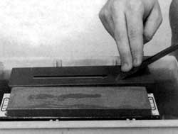
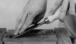
Using Oil Stones and Diamond Hones–Hold the bevel of the chisel on the hone. Slide the chisel over the hone with the cutting edge pointing in the same direction you are sliding the chisel (Figure 24-35). Think of it as trying to shave off a thin sliver of the hone. Turn the chisel over and repeat the procedure on the flat side.
Using Water Stones and Rubber Bonded Abrasives–To hone bench chisels With a cutting edge Wider than 1/2″, follow the oil stones and diamond hones instructions.
For bench chisels with narrower cutting edges, slide the chisel over the hone with the cutting edge pointing away from the direction you are sliding the chisel (Figure 24-36). Think of it as trying to smooth over the surface of the hone. Turn the chisel over and repeat the procedure on the flat side.
Grinding Planer and Jointer Knives
Jointer and planer knives need occasional maintenance. This upkeep consists of a simple cleaning and honing of the knives on the machine (see the Jointer or the Planer Owners Manual).
However, this type of edge repair will only go so far before the knives need to be removed and thoroughly ground. The best way to grind jointer and planer knives is to use the Shopsmith Grinding Wheel and Knife Sharpening Accessory that mounts on the Mark V. Set up the grinding wheel according to the Owners Manual that came with the Grinding Wheel.
Select the proper hard wheel for the severity of the cutting edge damage (coarse for nicks and a badly worn cutting edge and fine for routine grinding).
Warning: Never use the soft rubber-bonded abrasive or all-purpose wheels to grind jointer or planer knives. The sharp cutting edge of the knives will dig into the soft wheel and cause the knife to be thrown from your hands, causing serious hand cuts and damaging the wheel and the knife.
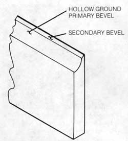
Remove the knives from the cutterhead according to the Jointer or the Planer Owners Manual. Planer and jointer knives are ground in a two-step operation. First, the primary bevel is ground. Then a secondary bevel is ground on the front edge of the primary bevel (Figure 24-37). This strengthens the cutting edge and helps dissipate the heat during cutting.
After the knives are used, they can be either honed in the jointer or planer, or reground on the secondary bevel. You will be able to regrind the knives in this manner several times until the secondary bevel becomes either wider than the primary bevel or wider than 1/8″.
Grinding Wheel Setup–Set the primary bevel angle by placing the knife on the knife rest in front of the knife guide. Loosen the wing nut and tilt the tool rest until the knife bevel is centered on the wheel (Figure 24-38). Warning: Position the tool rest no further than 1/8″ away from the wheel. Then tighten the wing nut.
Position the knife guide behind the knife so that it aligns the knife parallel to and just touching the wheel. Securely tighten the two screws that hold the knife guide in place. Remove the knife.
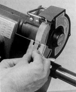
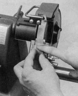
Grinding the Knives–Be sure that the speed dial is set to “Slow” Turn on the Mark V and set the speed dial to “R” (3500 RPM). Hold the knife firmly on one end of the knife rest and feel for it seating solidly against the knife guide.
The 4″ jointer knives are held with one hand and slid back and forth across the knife rest (Figure 24-39). The 12″ planer knives are ground in three overlapping sections (Figures 24-40A, 24-40B, and 24-40C).
Slide the knife slowly across the knife rest and knife guide, and past the wheel. Caution: Keep the knife moving. If you hesitate, the wheel will heat up the knife and turn the edge blue. This will ruin the factory heat treating.
Grind the knives at this setting until the sparking stops. When the sparking stops, the knife should be evenly ground.
If some of the nicks are still showing on the edge of the first knife, or only part of the bevel is ground, you may need to reset the guide and continue grinding the primary bevel. But if the remaining edge damage is minor or all but a slight part of the bevel is yet to be ground, the secondary bevel grinding operation will grind away and true up the edge.
Grind the primary bevel on the other two knives at this setting. Then turn the speed dial to “Slow” and turn off the machine.
Set the secondary bevel angle by loosening the Wing nut and resetting the tool rest approximately 10° to 15° toward the wheel. Tighten the wing nut. Place the knife on the knife rest and reposition the knife guide so that the knife just touches the wheel (Figure 24-41). Repeat the knife grinding procedures explained above, It should only take one or two passes to grind the secondary bevel.
It is not necessary to hone the jointer and planer knives after they are ground. The burr that is left on the cutting edge is small, and will be knocked off at the first contact with the stock.
Grinding Shaper Cutters
Two and three wing shaper cutters may be the most misunderstood cutters in the workshop when it comes to sharpening. It may appear that all the complicated curved wings, on each cutter, must be identically ground and then honed on their curved surfaces. Well this is only partially true and not nearly as difficult as it may sound. These cutters need only be accurately sharpened on the leading flat face.
For shaper cutters this is made easy be using the Shopsmith Sharpening Guide. By precisely grinding the face of each wing of each cutter, the cutting edge is sharpened.
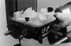
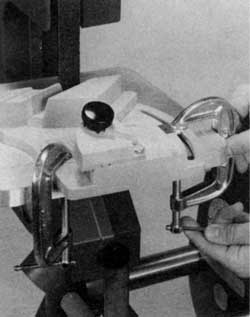
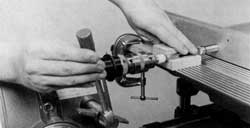
Mount the sharpening guide on the Mark V worktable and position it according to the Owners Manual. Mount the sanding disc and position it 3″ away from the worktable.
To mount the shaper cutter to the sharpening guide, first, slip the small rub collar on the 1/2″ shaper arbor. Then slide the arbor, from the bottom up, through the hole in the base of the sharpening guide.
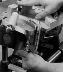
Slip the cutter over the arbor. Hold the cutter wing firmly against the face of the sharpening guide. Install the tongue washer and nut. Tighten the nut fingertight to hold the cutter in place (Figure 24-42).
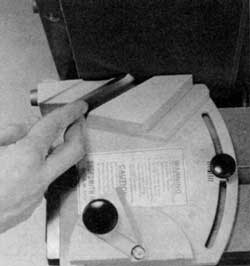
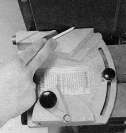
Adjust the sharpening guide to the “0” setting. Position the guide on the worktable until the disc will completely cover the face of the cutter when the quill is extended. Lock the sharpening guide securely in place (Figure 24-43).
Position the disc no further than 2″ away from the face of the cutter and lock the power plant lock. Extend the quill until the disc comes in full contact with the face of the cutter. Slight adjustments of the sharpening guide may be needed at this time to position the cutter face precisely in front of the disc.
Set the depth stop to “0” and lock it in place. When the quill is extended the abrasive will remove a slight amount of metal from the wing.
Be sure that the speed dial is set to “Slow”, then turn on the machine. Allow the abrasive to contact the cutter for only a moment then allow the quill to retract. Continue this until the sparking stops. Turn off the machine.
With the quill retracted, unplug the Mark V, loosen and remove the arbor nut and tongue washer holding the cutter in place. Slide the cutter off the arbor. Rotate the cutter so that the flat of the next wing is facing the disc. Replace the nut and tongue washer. While holding the cutter against the side of the sharpening guide, tighten the arbor nut securely.
Repeat the previous grinding steps without moving either the depth stop, carriage or the power plant. Rotate the cutter as described above to grind the third wing of the cutter. Then hone the face of each wing.
Honing Shaper Cutters and Router Bits
It is a simple matter to remove the grinding burr from a shaper cutter left by the abrasive. To avoid changing the cutter’s profile, do not hone its curved or beveled edges. Warning: Because of their size, router bits are not easily ground so it is recommended that these bits only be sharpened by honing the leading flat face.
To hone steel cutters and bits, start with a coarse hone (of any type) and progress to fine. To hone solid carbide or carbide tipped cutters and bits, you must use a diamond hone. As you progress, reduce the pressure applied to the hone.
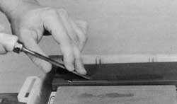
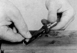
Lay the flat face of the cutter or bit on the flat top surface of the hone with the rest of the cutter overhanging the edge. Rub the cutter or bit up and down the hone (Figure 24-44). Be sure to hold the cutter flat against the surface of the hone while working it back and forth.
Count your honing strokes and hone each wing of the cutter or leading flat face of the bit an equal amount. This will assure equal metal removal and keep the cutter or bit properly balanced. The slight burr that may be created after the grinding burr is removed from the cutter will be knocked oft when the cutter first contacts the wood.
Honing Molder Knives
Warning: Molder knives should be honed only. Start with a coarse hone (of any type), then progress to fine. Lay the flat face of the molder knife cutting profile on the surface of the hone with the rest of the knife overhanging the edge.
To avoid changing the cutter’s profile, do not hone its curved or beveled edges. Hold the knife flat against the surface of the hone while working it back and forth. (Figure 24-45). Warning: Hone ONLY the area of the knife that cuts the wood. Do not hone the part of the knife that is held Inside the molder head. If the surface of the knife inside the molder head is thinned, the knife holding system will be weakened and the knife may break.
Count your honing strokes and hone each molder knife an equal amount. This will assure equal metal removal from each knife and keep the assembled molder head properly balanced. The slight burrs that may be created by honing will be knocked off the cutting edges when the molder knives first contact the wood.
Honing Lathe Duplicator Cutters
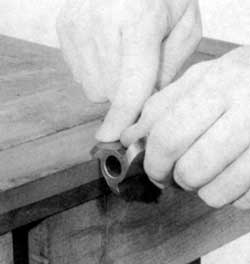
Warning: Lathe duplicator cutters should be honed only. To hone the solid carbide cutters (round, triangle, square or diamond), you must use a diamond hone. Warning: DO NOT attempt to grind the solid carbide cutters. The carbide dust is hazardous and may cause health problems.
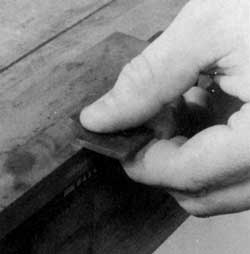
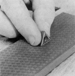
Lay the flat side of the square or triangle cutter on the surface of the hone. Hold the edge of the cutter flat against the surface while working it up and down the hone (Figure 24-46). Count your honing strokes and hone each side of the multi-sided cutters an equal amount. This will assure equal stock removal from each side of the cutter.
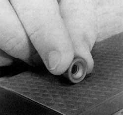
To avoid honing a flat spot in the round cutter’s profile, roll the cutter as it is honed (Figure 24-47).
To hone the cone (steel) cutter, start with a medium hone (of any type). Hone the cutter progressing from medium to ultra-fine. Use the edge of a curved slip stone to remove the burr on the inside of the cutter and produce a razor sharp edge (Figure 24-48). Each cutter can only be honed a few times before its size and profile are reduced so that it will not match the follower. When this happens, the cutter may be discarded or the follower can be sanded (by hand) with fine sandpaper to match the cutter.
Sharpening Mortising Chisels
The inside of the mortising chisels are ground and honed with special cone-shaped grinding stones mounted in the drill chuck. The outside is then honed on a flat bench stone.
Grinding Mortising Chisels
Even when new the chisels will usually need to be ground or at least honed. All four corners as well as the edges MUST be razor sharp. This is critical to the accurate operation of the mortising accessory.
Use the white conical grinding stone to sharpen the 1/4″ chisel, and the red conical grinding stone to sharpen the 3/8″ and the 1/2″ chisels.
To properly grind mortising chisels, a support fixture must first be made (Figure 24-49). The fixture will be mounted to the miter gauge. Set up the Mark V in the horizontal boring mode. Instead of mounting a drill bit in the chuck, install the proper grinding stone for the size chisel being ground.
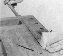
Clamp the support fixture on the table. Set the chisel on the fixture and back up the chisel with the rip fence. Hold the chisel against the fixture and the fence, and center the chisel on the grinding stone and lock the table in position.
Position the power plant, with the stone mounted in the chuck, so that the stone is 2″ from the chisel. Extend the quill until the stone touches the chisel and set the depth stop to “0” and allow the quill to retract. Warning: Be sure that the speed dial is set to “Slow,” then turn on the machine. Extend the quill until it contacts the chisel momentarily then allow it to retract (Figure 24-50). Repeat this until the stone ceases to remove any more metal. Inspect the tips and the edges of the chisel. Look for the grinding burr on all edges and the four tips. If there are still ungrounded surfaces or tips, repeat the above steps to remove additional metal.
If the stone becomes loaded with metal particles, it can be cleaned. Turn off the Mark V and apply a generous amount of oil to the stone. Rub the oil into the stone to lift out the metal particles.
Honing Mortising Chisels
After grinding is complete or the chisel has become slightly dull, hone the mortising chisel on a flat bench stone and the cone-shaped grinding stone.
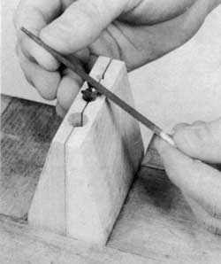
Lay the chisel flat on a bench stone and move it back and forth to remove the grinding burr from the outside (Figure 24-51). Count the strokes and hone each side of the chisel an equal amount.
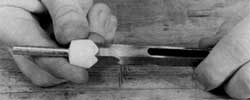
To remove the burr from the inside of the chisel, handhold the cone-shaped stone straight in the end of the chisel and rotate the chisel back and forth several times (Figure 24-52).
Repeat the honing on the bench stone with progressively finer stones along with the internal honing with the cone-shaped stones until the tips and edges are razor sharp.
Sharpening Mortising Bits
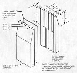
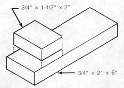
Figure 24-53. Construction details of a filing block for filing and honing mortising bits.
Along with the chisels, the bits must be periodically sharpened. They can be honed with contoured slips when only slightly dull, but must be filed and then honed after they become extremely dull. Clean the bit thoroughly before attempting to file or hone it.
Filing Mortising Bits
Before the bits can be filed you must make a filing block that fits in a vise (Figure 24-53). Use drill bits, not mortising bits, to drill the holes in the filing block. Mortising bits flair out at the tip and will drill an oversized hole.
Attach the filing block to the inside of the vise jaws with double-sided tape. Close the vise to within 1/16″. Slide the mortising bit in the proper hole with the cutting flutes of the bit parallel to the vise jaws and no more than 1/4″ above the top of the wooden blocks. Close the vise to clamp the bit in position (Figure 24-54).
File from the back of the cutting edge to the front on one of the side cutters. Count your strokes and repeat the same number of strokes on the inside surface of the other side cutter (Figure 24-55).
In a similar manner, hold the file on the “factory ground” bevel forming the bottom relief angle of the bit and file this surface. Count the strokes and repeat the same number of strokes on the other bottom relief angle (Figure 24-56).
The final filing steps are performed on the front of the cutting edge. This will remove the burrs created by the previous filing steps. Hold the file almost vertical against the front cutting bevel and push the file down along the bevel (Figure 24-57). Count the strokes and repeat the same number of strokes on the other front cutting bevel.
Honing Mortising Bits
In most cases the use of a fine enough file will sharpen the bit sufficiently. If there is a burr on the cutting edge, or tearing of the wood fibers during use, honing of the bit’s cutting edge will be necessary.
Use a fine contoured slip stone. A triangular or a teardrop shape works well. These are usually oil stones, rubber bonded abrasives, or diamond hones. All work equally well.
Hone only the inside edges of the two side cutters (Figure 24-58) and the two front cutting bevels (Figure 24-59). Do not attempt to hone the bottom relief angle on the bottom of the bit. Honing is done in the same manner as filing. Remember to count your strokes and hone each surface equally.