Wood joinery is one of the most rewarding parts of any woodworking project. Ranging from simple, attractive miter and bevel joints to the more complicated lock corner and finger joints, this tip will cover the wood joinery that can be done on the Mark V in the table saw mode.
Miter cuts
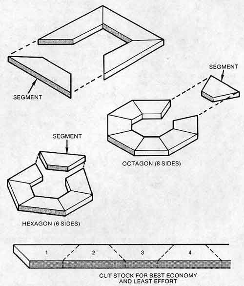
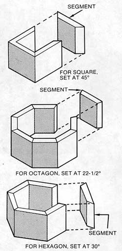
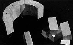
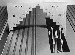
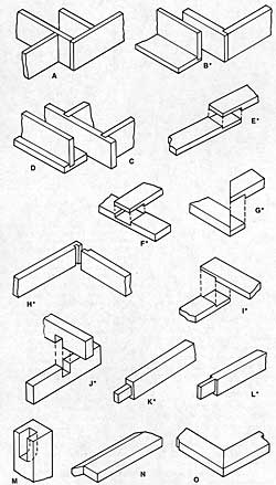
Both miter and bevel cuts are made with the stock held at an angle (other than 90°) to the saw blade. For instance, anytime you change the miter gauge from its normal 90° position, you will be sawing a miter. Some examples of miter cuts used to form four-, six-, and eight-sided figures are illustrated in Figure 3-1. The cut pieces, joined to make forms, are called segments.
It is important to remember that a miter cut angle is always one-half of the joint angle. The joint angle in a four-sided picture frame is 90°, but the cut angle is 45°. Use the following formula to determine the correct miter gauge setting for a project with any number of segments: Divide 360° by the number of sides and then divide the answer by 2. To apply this formula to an octagon, for example, divide 360° by 8; then divide the answer, 45°, by 2. This will yield 22-1/2°, which would be the correct setting for the miter gauge.
desired angle, and secure the lock knob. Warning: Place the miter gauge in one of the slots so that the face of the gauge is angled toward the blade. If you mount the miter gauge so the face is angled away from the blade, the wood may bind and kickback. Note: Since most miter cuts are made at 45°, the miter gauge has positive stops to help you quickly adjust the gauge to 45° left or 45° right. However, it’s wise to check critical setups with a drafting triangle or combination square.
Mark the workpiece where you want to cut it. (It’s best to measure from the inside corners of the miter.) Align the workpiece with the saw blade and clamp it securely with the miter gauge safety grip.
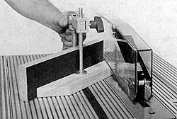
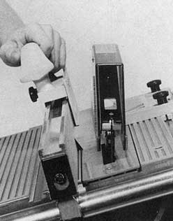
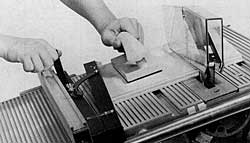
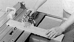
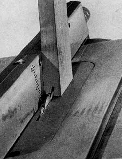
From this point on, the procedure is similar to crosscutting. Make a five-point check. All five locks-power plant, carriage, table height, table tilt, and quill-should be secure. Turn the machine on, set the proper speed and let the machine come up to speed. Push the workpiece slowly past the blade (Figure 3-2). When the cut is finished, turn the machine off and let the blade come to a complete stop before removing the workpiece or scraps.
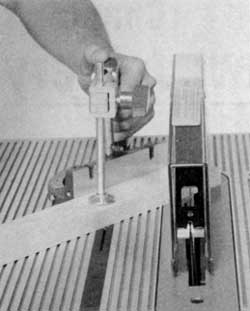
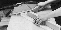
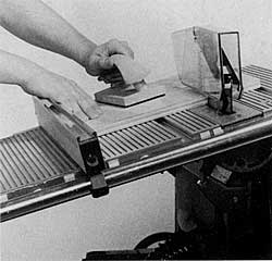
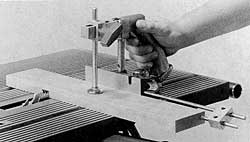
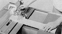
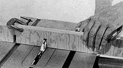
Miter sawing is no more difficult than straight crosscutting but accuracy is most critical. An error of 1° doesn’t sound like much, but when it’s repeated on even just four parts, it adds up to frustration at assembly time. Make it a habit to test machine settings on scrap stock. Saw the good material only when you are sure the setting is perfect. Guard against drift which is the tendency of the blade’s rotation to pull the workpiece-perhaps just enough to spoil a perfect cut. A fence extension that is faced with sandpaper helps keep the workpiece in place (Figure 3-3). Hold the workpiece securely; use the miter gauge safety grip.
Here are some things that will cause inaccurate miter joints:
- Improper alignment of the machine.
- Dull saw blade or incorrectly set teeth.
- Stock warped or otherwise imperfect to begin with.
- Stock allowed to drift.
- Pass made too fast.
Mitered segments must be perfectly matched in size and shape if they are to join together in a perfect union. Use this formula to determine the segment length:
Frame width – rabbet width x 2 + picture length = frame length
Example for 8″ long picture:
2″ – 3/8″ = 1-5/8″ x 2 = 3-1/4″ + 8 = 11-1/4″
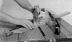
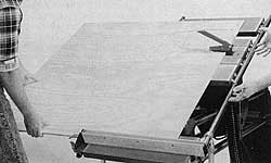
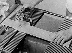
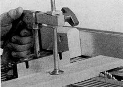
The miter gauge stop rod can be used as shown in Figure 3-4 to gauge the length of the segments. Square a piece of stock to this length. Set the miter gauge to the angle needed, and miter both ends of the segment. Then use it to set the miter gauge stop rod. Warning: Never position the miter gauge stop rod so that it crosses in front of the blade. Other segments are cut from one length of stock by mitering it at one end, then holding the mitered end against the stop rod. Be sure that you turn the stock over for each new pass.
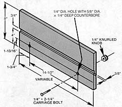
A miter gauge extension with an adjustable stop can be used to cut miters on wide stock (Figure 3-5).
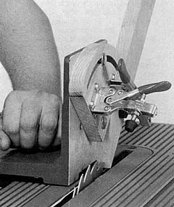
Miter Cuts with a Fixture
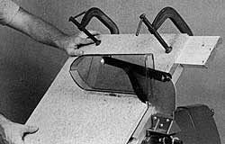
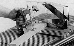
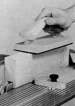
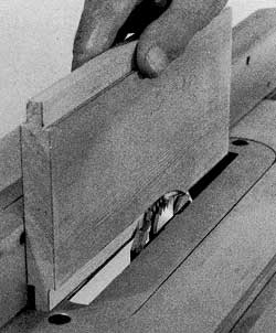
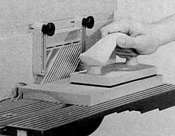
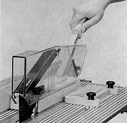
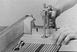
Cutting close, tight miters is much easier when you use a sliding table fixture (Figure 3-6). The fixture is easy to make and is well worth your time and effort, because a fixture that is well built and set up accurately will enable you to cut perfect 45° miters every time. The strips that slide in the miter gauge slots are cut to fit from hardwood. Use screws to secure the strips to the base; then cut a 12″ long saw kerf into the fixture.
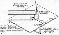

Miter one end of each hardwood fence at 45°. Use glue and screws to secure one of the fences into place at 45° to the saw kerf. Once the glue on this fence has dried, use an accurate square to position the other one; secure it with glue and screws. So that the stock will have less tendency to drift while being cut, attach fine grit sandpaper onto the fixture with rubber cement.
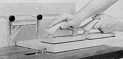
When using this fixture, always cut matching miters. This is done by cutting the first corner of the stock on the right side of the fixture and the second corner on the left side.
Remember that all fixtures, in addition to being carefully made, should be protected so they will maintain accuracy. Carefully sand all parts before assembly. Use glue and screws to join components. After assembly, apply several coats of penetrating sealer with a light sanding between coats and another light sanding when the final coat is dry. Wax and buff those surfaces that make contact with the machine.
Bevel Cuts
Bevel cuts are made with the worktable positioned at an angle other than 90° to the blade. Slide the carriage and the power plant all the way to the right. This will allow you to move the workpiece freely across the table without interfering with the way tubes. The angle considerations that apply to miters also apply to cross miters and bevels (Figure 3-7). The cut angle is always one-half of the joint angle.
Crosscut Bevels
To make a crosscut bevel, set the worktable at the desired angle and use the miter gauge to guide the workpiece (Figure 3-8). Mount the miter gauge on the downside of the table only. This will provide better support for the workpiece, help eliminate kickbacks, keep the miter gauge from hitting the blade, and keep your hands out of danger.
Rip Bevels
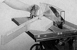
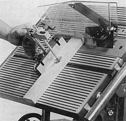
A rip bevel is made with the table tilted, the workpiece usually riding against the rip fence (Figure 3-9). Warning: Mount the rip fence on the downside of the table to provide better support for the workpiece, help eliminate kick-back, and keep your hands out of danger. On the Model 500 there will be times when the width of a workpiece will prevent you from using the rip fence. If this is the case, clamp a long, straight board to the underside of the workpiece and rest this board over the upper edge of the table (Figure 3-10). If properly positioned, the board will guide the workpiece as accurately as a rip fence. If you have a Model 510, use the rip fence and the extension table system to support wide stock (Figure 3-11).
Small, cross beveled or rip beveled segments are easy to assemble if you work as shown in Figure 3-12. Coat mating surfaces with glue and hold them tightly together as you drive staples to serve as “clamps.” Use a band clamp or rubber bands after the assembly is complete to hold the pieces together until the glue is dry.
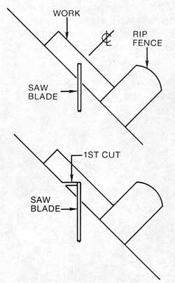
A convenient way to cut beveled segments is shown in Figure 3-13. First cut the segments to the length and width you need. Set the table to the correct tilt and the fence to control the width of cut. Cut the bevel on one edge of the stock and then, without changing the setting, turn the stock end-for-end and bevel the second edge.
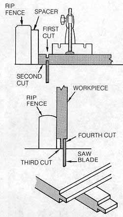
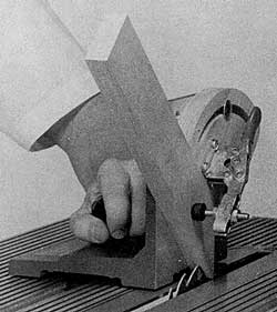
V-cuts
V-shapes are formed by opposing bevel cuts that do not go through the stock and which meet to form an angle. Work as shown in Figure 3-14 when the “V” must be down the center of the stock. Set the saw blade’s projection to the depth of the “V” needed. Set the rip fence so the center of the workpiece will match the topmost point of the saw blade. Make one pass and, after turning the stock end-for-end, make a second pass. Warning: Be sure to stand to one side when you make the second pass because the V-shaped waste piece might be kicked back toward the front of the table by the action of the saw blade.
V-cuts that are not centered are done almost the same way. The difference is that the rip fence must be relocated to position the workpiece for the second pass.
Compound Angles
While a miter cut requires a miter gauge setting and a bevel calls for a table tilt, a compound angle cut is done with a combination of both settings.

Any frame or open structure that has sloping sides requires a compound miter (Figure 3-15). Typical examples of projects that have compound-angle miter joints include: a peaked figure with any number of sides such as you might require for a fencepost top or the roof of a birdhouse or doll-house, a plant container with sloping sides, and a picture frame with sides that slope toward or away from the wall.
Of all table saw operations, compound angle cuts are probably the hardest to do, not because of how they relate to sawing, but because the accuracy of the cut is so critical. Work slowly; be sure of each setting before you cut into good stock. Here is a good procedure to follow: Adjust the miter gauge to the angle you need and make a test cut with the table set at “0”. Check to see if the cut is correct. Tilt the table to the angle required and make a test bevel cut. Check to see if that cut is correct.
Compound cutting sometimes requires alternating the miter gauge in the table slots, which means the miter gauge setting must be changed each time. Check each setting carefully before making the pass. Some woodworkers have an extra miter gauge on hand for just such times.
Take a stance that keeps you out of the line of cut and make a test pass without the workpiece and with the power off, so you can preview the best way to handle the operation.
Here is a typical procedure, based on a four-sided frame and using the popular 60° work angle, which may be followed when doing compound angle work. Note: The work angle is the angle measured between your line of sight and the flat face of the frame. First decide the overall size of the frame and from this determine the lengths of the four pieces required. Cut and square these pieces to exact length as if it were a simple frame.
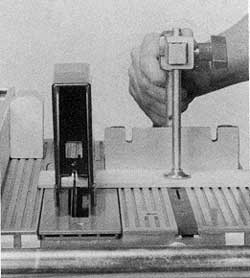
By referring to Table 3-1, you will discover that the 60° work angle requires a table tilt of 20-3/4° and a miter gauge setting of 49°. Set the miter gauge and the table exactly at these settings. If you are off even a fraction of a degree, you won’t get a good joint. To gauge the amount of cutoff, you can clamp a stop block to the table or use a miter gauge stop rod so the work can be positioned correctly before making contact with the blade. Hold the workpiece very firmly by using the miter gauge safety grip and make the pass very slowly (Figure 3-16). The four parts should fit together snugly, while forming a perfect right angle at each corner.
This method does involve wasting some wood, but attempting to cut each part of the frame con-secutively from one long board or calculating the exact length is extremely difficult. Cutting the four pieces to exact length beforehand, as suggested, pays off in accuracy and convenience.
Work with the taper guide when you need to cut a compound angle on a wide piece of stock (Figure 3-17). In effect, the taper guide is a substitute for the miter gauge. The difference between this operation and normal taper cuts is that, here, you work with the table at a tilt angle.
Dado Accessory Joinery
In joinery and some other special applications, it is often necessary to make a cut considerably wider than the saw kerf. For this type of work, a dado accessory is usually used.
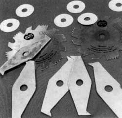
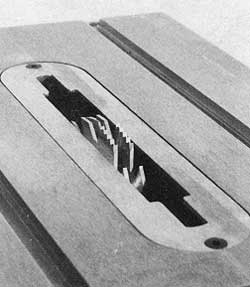
A dado accessory (Figure 3-18) consists of two outside blades, four 1/8″ and one 1/16″ chippers that are used between the blades. Width of cut, which can range from 1/8″ to 13/16″, is controlled by the number of components that you mount. A single outside blade will cut a 1/8″ kerf; if you mount the two blades, the cut will increase to 1/4″. You must add chippers to go beyond 1/4″. For example, for a 1/2″ cut, use both outside blades and two 1/8″ chippers. To increase the kerf to 9/16″ wide, add the 1/16″ chipper. Since there can be some minute variation in nominal wood and even plywood thicknesses, paper washers are supplied for mounting on the arbor between the components; thus you can make slight adjustments in width of cut.
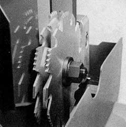
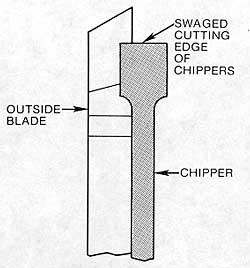
The dado accessory is mounted on a 5/8″ molder/dado arbor which locks on the Mark V’s main spindle (Figure 3-19). Warning: Be sure the tongue washer is used under the hex nut and the threaded shaft of the arbor is flush or extends past the end of the hex nut. Never use chippers alone or mount chippers with only one outside blade, because a kick-back hazard is created. Arrange chippers so they are evenly distributed and so their swaged cutting edges align in the gullets of the outside blades (Figure 3-20).
Because the dado accessory makes extra-wide cuts, you must use a special table insert that accommodates it (Figure 3-21). Warning: Be sure that the dado accessory has clearance in the slot. Rotate it by hand, using the auxiliary spindle, before turning on the power.
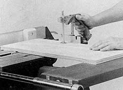
The projection of the dado accessory is always less than the thickness of the stock. You can set projection by using a measuring scale or a step gauge (Figure 3-22).
You work with a dado accessory in much the same way as you do a saw blade, but since the tool will be removing much more material, the pass should be made very slowly to give the blades a chance to work without clogging. Form extra-deep cuts by making more than one pass. For example, if you need a cut that is 1-1/4″ deep, make one pass with the cutter’s projection at about 5/8″. Make a second pass after adjusting the saw table for the full 1-1/4″ deep cut. This procedure is especially applicable if you are working with a hardwood like oak or maple. Warning: The dado accessory is used without the upper saw guard in place. Whenever you remove the upper guard, keep the lower guard in place and make sure the lock knob is secured. Use a push stick, push blocks and safety devices. Work with extreme caution.
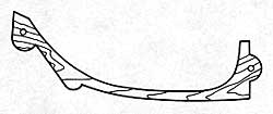
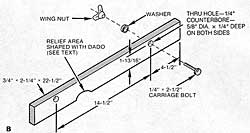
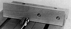
Guard Spacer (Mark V with Metal Lower Saw Guard Only)- Because the dado accessory can be used for extra-wide cuts, you must place a spacer (offered free through Customer Service) between the two halves of the lower saw guard. If you want to make a spacer, remove the cover from the guard and trace its contour on a piece of 1-1/4″ stock that measures 3-1/2″ wide by 10″ long. Mark the location of the bolt holes and then draw another line parallel to the first one but about 1/4″ smaller. Cut the stock on a bandsaw or scroll saw, and drill 9/32″ holes for the attachment bolts. When you are finished, the spacer should look like the one shown in Figure 3-23. Secure the spacer between the two halves of the lower saw guard with 1/4″-20 x 1-3/4″ bolts.
Dadoes
A dado is a U-shaped square cornered cut in the surface of a board that is made across the grain. Use the miter gauge and the safety grip as you Would for any crosscutting operation. When you need the same dado on more than one piece of stock, you can work with the miter gauge stop rod (Figure 3-24) or the miter gauge extension with the sliding stop to position the workpiece so the cuts will be the same on all pieces. Warning: Never position the miter gauge stop rod so that it crosses in front of the blade.
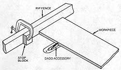
Extra-Wide Dadoes-When you need a dado that is wider than can be accomplished with the dado accessory at maximum width, proceed as follows: Place a spacer on the rip fence near the front of the table and lock the fence so the distance from the spacer to the dado will be the edge distance of the cut you need. Butt the end of the work against the spacer and make the first cut (Figure 3-25).
Next, move the rip fence so the distance from the spacer and the outside surface of the dado accessory will be the width of the cut you need. Make a second cut (Figure 3-26). Then just keep making overlapping passes until the waste stock between the first two cuts has been cleared away (Figure 3-27).
Grooves
Grooves are U-shaped cuts that are made with the grain of the wood. They are made much like rip cuts, with the fence positioned to gauge the distance between the cut and the edge of the stock. Figure 3-30A shows a groove being cut in the surface of a workpiece. A feather board mounted on a rip fence extension helps to keep the workpiece down against the table.
To cut grooves in the edge of a workpiece, position a feather board in front of the dado accessory. Use a push block to move the stock (Figure 3-31).
Other Dado Accessory Joinery
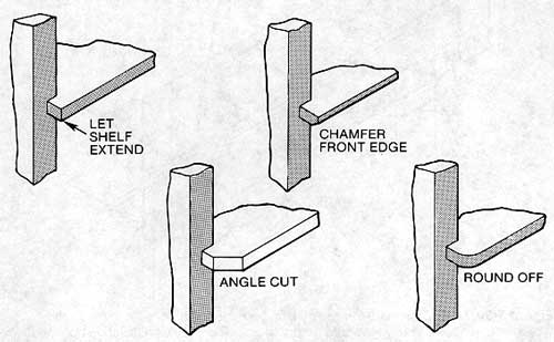
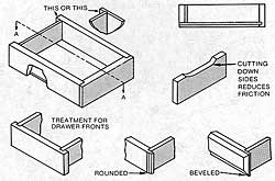
All of the joints that are shown in Figure 3-32 can be cut by using a dado accessory. A problem with the simple dado joint is that it leaves a visible joint that is not attractive (Figure 3-33). The lines are hidden when the project is designed with facing strips or a front frame (Figure 3-34). To create a more acceptable appearance when the joint can’t be hidden, you can install shelves that are wider than the sides of the case. As shown in Figure 3-35, the front edges of the shelves can be treated in various ways to contribute to visual appeal.
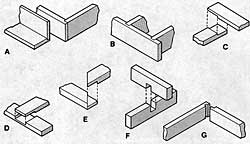
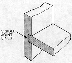
Figure 3-33. A disadvantage of the dado joint is that its joint line is visible.
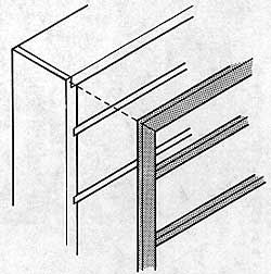
Figure 3-34. The joint lines are hidden if the project calls for facing strips or a front frame.
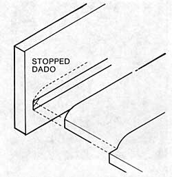
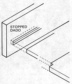
A very professional way to conceal dado joint lines is to work with stopped dadoes. This simply means that the dado cut is not continued completely across the stock. To control the length of the cut, you work with a stop block secured to the rip fence (Figure 3-36). This, of course, leaves an arc where the cut stops. The shelf, or whatever insert, can be shaped in one of the ways shown in Figure 3-37 to accommodate the arc. Another method is to use a small chisel to cut away the arc material so shelves can be inserted as shown in Figure 3-38.
Rabbet Cuts-A rabbet is an L-shaped cut made on the end of stock or along the edge. The width of the cut may be gauged with the miter gauge stop rod or by using a spacer on the rip fence. Warning: Never position the miter gauge stop rod so it crosses in front of the dado accessory.
When rabbet cuts are needed along the length of stock (this may be called for when the back of a bookcase or other project is recessed into the frame), the rabbet is cut with the stock sliding against the rip fence.
The size of the rabbet is deter-mined by the piece that will be joined to it. For example, if you were recessing a 1/4″ panel into the back of a bookcase frame made of 3/4″ stock, the rabbet would have to be 1/4″ deep (to accommodate the panel) by about 3/8″ wide (to provide fastening area without loss of strength to the side).
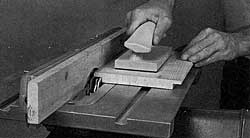
While rabbets can be cut with a conventional saw blade as described later in this chapter, they are more easily formed with a dado accessory. To obtain the most accurate results, make a fence facing like the one shown in Figure 3-39. To form the relief arc that is needed in the facing, continue in this manner: Raise the table above the dado accessory and bolt the facing to the rip fence. Lock the fence so the dado accessory will cut about three-quarters of the facing’s thickness; then very slowly lower the table until the arc’s height is about 3/8″ deep.

o form an edge rabbet, lock the rip fence so the distance from the fence facing to the outside of the dado accessory equals the width of the rabbet. Adjust the blade projection for the depth of the rabbet. Hold the workpiece snugly against the facing and make the pass as shown in Figure 3-40.
End rabbets may be cut in similar fashion but a spacer is mounted on the rip fence and the miter gauge with safety grip advances the work (Figure 3-41). The rip fence is locked so the distance from the spacer to the outside of the dado accessory equals the width of the rabbet; the blade’s projection is set for the rabbet’s depth. Figure 3-38. The arc area of the stopped dado can be cleared out with a chisel; the shelves can then be fitted this way.
Tongue-and-Groove Work-To perform tongue-and-groove work, assemble the dado accessory so you’ll get the groove width you need. Set the projection for the depth of the groove; then make the pass as shown in Figure 3-42. Be sure that the stock has ample bearing surface against the insert. To ensure that the groove will be exactly centered, assemble the dado accessory parts to make the cut narrower than you need. Make one pass and then turn the stock end-for-end and make a second pass.
The tongue is formed by making two opposing rabbet cuts on the stock’s edge (Figure 3-43). Make a first cut with one side of the stock against the fence and make a second cut after turning the stock end-for-end. It’s easier to make adjustments for the rabbet cuts that form the tongue, so always shape the grooves first and fit the tongue to the groove.
Forming a Tenon-A tenon can be formed by making two matching rabbet cuts, controlled by the setup shown in Figure 3-44. The distance from the spacer to the outside of the dado accessory equals the length of the tenon. The blade’s projection equals one-half of the stock’s thickness minus half the thickness of the tenon. Make repeat passes to clean away the waste stock; then turn the work over and repeat the procedure (Figure 3-45).
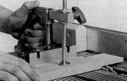
Figure 3-45. To finish the tenon, turn the stock over and repeat the procedure.
Additional Joinery
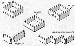
All of the joints shown in Figure 3-46 can be accomplished by working with either a saw blade or a dado accessory. Some of the joints can be made using the Tenon Master Jig. It’s a good idea to become familiar with these joints since they are used in many types of furniture and cabinetmaking and in drawer and case constructions.
By making repeat passes with the saw blade you can form dadoes, grooves and rabbets.
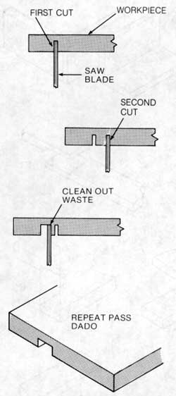
Dadoes-Figure 3-47 shows how to form a dada by making repeat passes with a saw blade. The first and second cuts form the shoulders of the dado. The material between the two cuts is removed by making overlapping passes. When the same cut is required on more than one piece, gauge the first and second cuts by using a stop block on the rip fence and miter gauge extension or stop rod. Warning: Never position the miter gauge stop rod so it crosses in front of the blade. Do the cuts in sequence on all pieces; that is, make the first cut on all pieces and then the second cut. This will ensure that the cuts will be similar and correctly located on all the work.
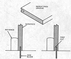
Grooves-A repeat-pass groove is formed by working against the rip fence as diagrammed in Figure 3-48. Work this way to assure that the groove will be exactly centered. Mark the stock for the first cut; this will indicate the stock thickness that remains after the groove is formed. Set the fence so the outside of the blade will be on that line and make the first pass. Then, turn the stock end-for-end so the opposite surface will be against the fence, and make a second pass. If material remains between the two cuts you can clear it away by making additional passes. On jobs like this, and especially if the stock is thin, make a special insert so there will be ample support area for the stock around the cut area. Use a rip fence extension and a feather board for additional support.
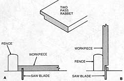
Rabbets-While rabbets can be formed with a dado accessory as described earlier in this chapter, they can also be made with a saw blade by following the two steps shown in Figure 3-49.
Use a rip fence extension and a feather board for both steps. Warning: Avoid getting the waste stock caught between the rip fence extension and the blade on the second cut; otherwise, the waste may kick back. Plan ahead carefully.
Cut the surface of the workpiece first (Figure 3-50). Then turn off the Mark V and readjust the position of the fence if necessary. Turn the workpiece on edge and make your second cut so that the waste is on the opposite side of the blade from the rip fence (Figure 3-51).
Notching
A notching cut is a dado that is cut across the thickness of the stock. When the cut is used to join pieces that cross each other and which must have even surfaces, the blade projection must be exactly one-half the stock’s width. A typical application is the eggcrate-type construction shown in Figure 3-52. One way to work is to clamp together all the pieces you need and saw them as if they were a single block (Figure 3-53).
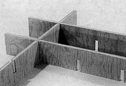
Mark the spacing between notches on the fron piece; set the dado width to equal the thickness of the stock and the blade projection to equal one-half the stock’s width.
Splines and Keys for Reinforcement
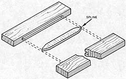
It’s always a good idea to reinforce a joint even though modern adhesives provide a strong bond. Splines, which can be used with many joint designs as shown in Figure 3-54, do an excellent job of providing the extra strength. A spline is simply a straight strip that is cut to fit grooves formed in the mating pieces (Figure 3-55). Since wood can split more easily along its grain than across its grain, splines should be designed so the grain is at right angles to the pieces to be joined.
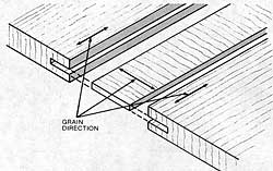
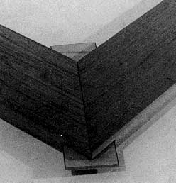
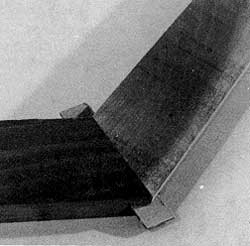
Figure 3-56 demonstrates how splines are used to reinforce simple miter and compound miter joints.
Forming Splines-One way to form splines is to first cut grooves through the ends of a workpiece and then to cut off the ends by doing a crosscut as shown in Figure 3-57. The thickness of the splines will depend on how you set up for the initial groove cuts. The grooves must run across the stock so the splines will have correct grain direction.
Plywood is an excellent material for splines. It provides a lot of strength and you don’t have to worry about grain direction. Cut the plywood to a width that equals the spline length you need and then simply cut off as many pieces as you need (Figure 3-58).
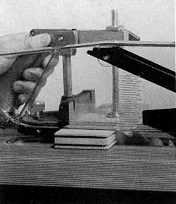
Blind Spline Joint-Simple butt joints are often used when boards are joined edge-to-edge, but a spline can aid in the alignment of the boards and add strength to the assembly. A blind spline can’t be seen (Figure 3-59). Warning: The upper saw guard is removed for this operation so work with extreme caution.
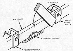
Cut the groove as shown in Figure 3-60. The stop blocks, clamped to the rip fence, control the length of the groove. Brace the workpiece against the front stop block, as shown in the illustration; then very slowly and carefully lower it until it contacts the dado accessory and rests securely on the table. Then move the workpiece forward until it contacts the rear stop block. Lift the work carefully when you remove it, picking the back end up first.
The splines, which are shaped dado, should have grain running across the short dimension. Always cut the grooves first since it’s no chore to form the splines to correct thickness. Don’t size the splines so they must be forced into place. A slip-fit is best since it makes assembly easier and provides room for glue.
Spline Grooves in Compound Miters-One method of forming spline grooves in compound miters, with the table tilted to the correct angle and the rip fence used as a guide, is shown in Figure 3-61. The operator is responsible for holding the stock securely and maintaining its position throughout the pass. Warning: The upper saw guard is removed for this operation so work with extreme caution. An easier and more accurate method is to use the Tenon Master Jig.
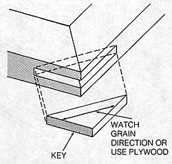
Keys-Keys are triangular pieces that are often used in the manner shown in Figure 3-62 to reinforce miter joints. Notice the direction in which the grain should run. The thin stock you need to make the keys can be cut as shown in Figure 3-63. To keep small pieces of stock from falling through the table insert, position the blade as close to the left side of the insert as possible.
Always cut splines and keys so they are longer than you need. It’s better to trim them and sand them to conform to project surfaces after they are installed and the glue is dry.
Tenons
The “true” tenon is shown in Figure 3-64. The tenon can be formed on the table saw with a dado accessory or by making multiple passes with a saw blade. Note: The “mortise,” which is a rectangular cavity that receives the tenon, is cut with a mortising, routing or drilling accessory.
The four-pass procedure illustrated in Figure 3-65 is generally used to form tenons. (This method can also be used to cut tongues.) Set the rip fence to, in effect, gauge the thickness of the projection. Make the first pass, and then make a second one after turning the stock end-for-end. Re-move the waste by working with the miter gauge. Since the last two cuts must match, gauge the stock’s position by using a spacer block on the rip fence.
The open tenon has only two shoulders. It and the slot it needs can also be formed on the table saw (Figure 3-66).
When forming tenons, the stock must be held on edge and components that require the cuts are often narrow, so the easiest and most accurate way to form tenons is to work with the Tenon Master Jig.
Form tenons by using a dado accessory or saw blade and working as shown in Figure 3-67. Once the Tenon Master has been correctly positioned, its position does not have to be changed. Make the first pass, turn the work so its opposite surface is against the face, and make a second pass. The work will be most secure when clamped to the face of the Tenon Master.
Slots can be formed by using a dado accessory or by making repeat passes with a saw blade (Figure 3-68). This is also a good way to form the initial grooves in stock ends which will then be crosscut to produce splines. In addition, you can work this way for the first cut when doing a two-pass rabbet, the first cuts for tenons, and so on. When the cut or the size of the work requires it, make a special table insert and use it instead of the standard insert.
The Tenon Master can be used for operations like forming grooves in miter joints for splines or keys. It positions the workpiece at the correct angle and secures it so it can’t move during the pass.
To accurately cut grooves for keys be sure the trunnion is positioned correctly. The mating pieces of the miter joint are set and locked in place as shown in Figure 3-69. When you work this way, it isn’t necessary for the grooves to be exactly centered. This same setup can be used to cut grooves for splines (Figure 3-70).
Finger Joints
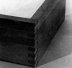
The finger joint, like the dovetail, is often found on classic examples of furniture. It is sometimes hidden, but other times it is left exposed to denote craftmanship and display the interlocking fingers which form interesting patterns (Figure 3-71). Structurally, it is an impressive joint because it has an unusual amount of gluing surfaces. It is often called a “box joint” which doesn’t exactly seem correct since the term connotes unimaginative applications. Actually it can be used on drawers, jewelry boxes, carcass constructions, and so on.
Generally, the width of the fingers should be about equal to the thickness of the stock. However, on a shallow project made of 1/2″ or thicker material, such heavy fingers would not be visually appealing. In many cases, even on deep projects made of thick material, thin fingers look more impressive. A good, practical finger width is 3/8″. This will look good on material thickness ranging from 3/8″ to 1″.
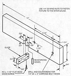
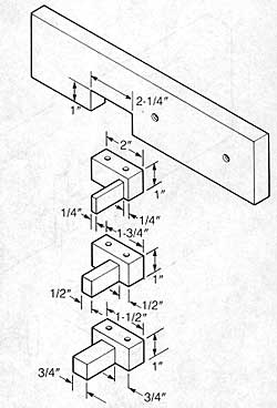
Finger joints look complicated. But when you make a simple fixture, like the one shown in Figure 3-72, you can cut mating pieces of the joint at the same time and with ensured accuracy. So that the mating pieces of the joint will fit snugly together, be very careful with measurements and cuts when you are making the fixture. Note: The fixture is for 3/8″ wide fingers only. For different size joints, the 3/8″ dimensions need to be changed to the sizes desired. Warning: The upper saw guard is removed so work with extreme caution.
To cut the notches in the fixture, set the dado accessory for a cut that is exactly 3/8″ wide. Set the dado blade’s projection to match the thickness of the stock or just a fraction more. Mount the fixture to the miter gauge and make the pass that cuts the first notch. Make a second notch exactly 3/8″ away from the first one. The guide must be exactly the width of the cut and be secured in the second notch with a screw.
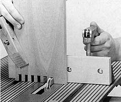
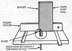
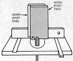
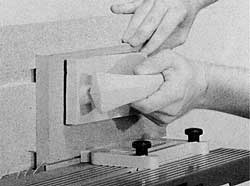
Figure 3-73 shows the fixture mounted to the miter gauge and ready to use. Place the spacer against the guide in the fixture and butt one piece of the workpiece (part one) against it. Make the first pass (Figure 3-74A). This first cut, which will be L-shaped, is then butted against the guide. The mating workpiece (part two) is put over top of part one. The uncut edge is butted against the guide (Figure 3-74B). Subsequent cuts are accurately spaced by fitting the preceding cut over the guide (Figure 3-75).
The finger joint fixture that we have demonstrated will continue to serve anytime the joint will have the same finger widths for which the fixture is designed. However, you can make another fixture that allows multiple width fingers if you interchange multiple size of guides (Figure 3-76). Using this type of fixture will require more care, since the fixture must be accurately set for each job.
When using either fixture, any excess of finger length can be sanded off after project assembly.
Lock Corner Joints
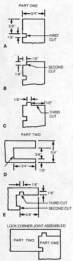
Joints of this type are a challenge to do, but they hold together beau-tifully. Figure 3-77 shows the typical procedure on 3/4″ stock. Accuracy is critical.
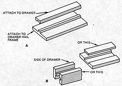
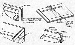
Joint Applications
Joints are used to hold parts together. The joints can be simple or advanced, but all must be carefully cut if they are to look good and hold with maximum strength. Figures 3-78 through 3-81 illustrate some joint applications on typical woodworking projects.

