Molding operations are performed with the Mark V in the table saw mode. The molder head accessory enables you to add professional detail to almost any project. With it you can shape edges and surfaces, form cabinet door lips, make sash moldings, produce strong glue joints, and do many other operations. Once you become acquainted with the tool, you’ll find that you can reproduce many standard wood patterns and also create virtually unlimited original molding designs. In a sense, it allows you to do decorative edging on the table saw.
The molder head (Figure 5-1) is a heavy steel disc that is mounted on the 5/8″ molder/dado arbor, then onto the Mark V’s main spindle.
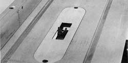
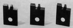
Because the molder head works with knives that are 1″ wide, it must be used with a specially designed molder insert (Figure 5-2). If the knife projection is small, make a hardboard insert for additional stock support around the cutter.
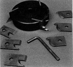
Figure 5-1. The molder head is a thick, heavy steel disc that has equally spaced slots around its perimeter to receive sets of molder knives. A special 5/8″ molder/dado arbor (not shown) mounts the molder head to the MARK V main spindle.
Use speed setting Q (3250 RPM) for hardwood and R (3500 RPM) for softwood.
Molding Safety
Warning: Before using the molder head accessory, read and understand these important safety instructions:
Danger Zone–The danger zone extends 3″ out from the knives on all sides, 2’in back of the knives, and 8′ in front of the knives. The reason for the extended danger zone in front and back of the knives is because of the danger of kickback.
- Read and understand your Table Saw Safety.
- When the molder head accessory is used, it is necessary to remove the upper saw guard. Whenever the upper saw guard is removed, keep the lower saw guard in place and work with extreme caution.
- Never use the molder head accessory without the molder insert installed. After installing the molder insert, turn the upper auxiliary spindle by hand to be sure the knives clear the insert.
- Make sure the setscrew In the molder/dado arbor is tightened against the flat of the main spindle, the tongue washer is installed next to the hex nut, the threaded shaft of the arbor is flush with or extends past the end of the hex nut, and the hex nut is securely tightened.
Molder Knives
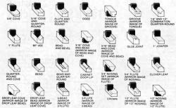
All of the knives shown in Figure 5-3 are available for use with the molder head. This is quite an extensive assortment, but it isn’t necessary to acquire all of them at once. Start with a few sets that will allow you to make a few basic cuts. Other sets can be added as you become more experienced with molder operations and as the need arises.
Knives, which come in sets of three matched cutters, are designed like the glue joint set in Figure 5-4 for full profile cuts; that is, the entire width of the knife is used to cut the shape in the wood.
The set shown in Figure 5-5 is designed so only part of the edge is used to cut, in this case, flute and quarter-round shapes. However, the full profile may be used if the shape pleases you.
Other examples of partial-cut knives are shown in Figure 5-6. The different shapes that each knife will produce depend on how you set up for the cut and, sometimes, how many passes you make.
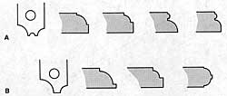
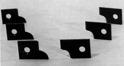
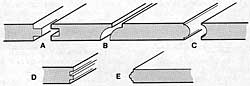
Knives, like the drop leaf table joint shown in Figure 5-7, are also available in matched sets. In this case, one set of knives forms the edge of the table, and the remaining set makes the matching cut on the hinged leaf of the table. Examples of three matching joints and two full-profile cuts are shown in Figure 5-8.
Knives may also be used in combination; that is, different knives may be used on the same piece of wood to produce a particular shape (Figure 5-9). The possible results are limitless, and with a good assortment of knives you could closely duplicate any molding shape that is displayed in any lumberyard.
Mounting the Knives–The molder head has three slots equally spaced around its perimeter. Each of the slots has its own prevailing torque setscrew which bears against a steel ball that will seat in the beveled knife hole when the setscrew is tightened. Warning: Be sure the slots in the molder head and the knives are clean. Any dirt that keeps the knives from seating correctly will cause inaccurate cuts and can be dangerous.
Hold the molder head so the slot points toward you and loosen the knife retaining setscrew. Tilt the molder head a bit so the ball moves out of the slot and then, approximately centering the knife, slip it into place. Just before the ball contacts the knife, move the knife side-to-side as you tighten the setscrew. This will center the ball in the hole. The knife will adjust itself to the ball and each knife will be aligned as you secure the setscrew. Caution: Do not over-tighten the screws. This will damage the knife, making it difficult to remove. Recheck the knives between jobs. Be sure the knives are correctly seated and that the set-screw is tight. The cutting edge of the knife is always on the side toward the setscrew. When the molder head is mounted on the spindle, the cutting edges will point toward the front of the worktable.
Since the profile of the knife is not the profile cut in the wood, you should keep sample cuts of the knives you acquire. These can be overlaid on a drawing of the shape you intend to produce so you can decide which profile, or which part of a profile, should come into play. Many molder knife profiles are duplicates of classic forms. Therefore, these sample cuts can be used as templates when planning designs, not only for molder work, but also when you are planning projects for lathe turning.
Molding Operations
Warning: Since many molder operations are best done by providing bearing surface close to the cutting area, the first thing you need to do is makearip fence extension.
Construction details of the fence extension are shown in Figure 5-10. If the holes for the bolts are counterbored on each side of the fence, you can secure it to either side of the rip fence, so you will be able to work with the fence on the left or right side of the table. Warning: Never position a feather board over the molder head. Position feather boards in front of or behind the molder head.
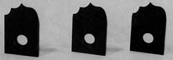
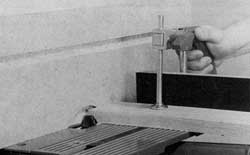
To make the arched relief area for the knives, mount the set of knives you are going to use in the molder head and, with the worktable elevated above the accessory, lock the fence so the knives will cut most of their width into the fence extension. Turn on the ma-chine and very, very slowly lower the table until the knives have formed an arch the maximum depth needed.
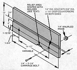
Figure 5-10. Construction details of the rip fence extension. if you counterbore for the bolt heads on both sides of the fence, you’ll be able to attach it on either side of the rip fence for use on the left or right side of the table. Click on image for larger view.
Molder cuts remove a lot of material, so passes should be made slowly, allowing the knives to cut without choking. A slow pass also results in smoother cuts, since the knives will be working longer on any given area of the wood. Make very deep cuts in stages, lowering the table or adjusting the fence position after each pass until the full cut depth or width is reached. Some warning signs that indicate you are cutting too deeply or too fast include rough cuts, the molder slowing, and the work beginning to chatter.
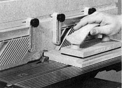
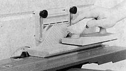
Cuts that are made on stock edges are handled as shown in Figure 5-11. Smoother shapes result when you place the stock so you are cutting with the grain of the wood. This isn’t always possible, so when you must work against the grain, feed the work even more slowly than usual.
Cuts made on stock ends can be held securely when you work with the miter gauge and safety grip (Figure 5-12). Warning: Use the miter gauge with safety grip to hold stock less than 10″ wide. It is difficult and unsafe to try to handhold such work.
Cuts that are made across the grain will always have slight imperfections at the end of the cut. To compensate, slow down when near the end of a cut or work with stock that is slightly wider than you need. A trim cut, made by ripping or jointing, can then bring the stock to correct width while removing the flaw.
When a project component requires that adjacent edges or all four edges of the piece be molded, make the cross-grain cuts first. The final cuts, made with the grain direction, will remove those slight imperfections that are characteristic at the end of cross-grain cuts.
Slim Moldings
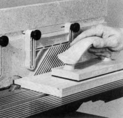
If you need a single piece of narrow molding, it is safer to form the shape on a piece of wide stock that you can safely handle and then rip to remove the shaped edge. If many similar narrow pieces are needed, you should organize for the operation as shown in Figure 5-13.
Pre-cut workpieces to size on the table saw. The feather boards are positioned to suit the height and width of the workpieces. The best procedure is to push the workpieces at the infeed end without allowing the workpiece to stop. Warning: Use a small piece of scrap to push the workpiece past the cutter. Support long pieces with a roller stand.
Surface Molding
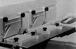
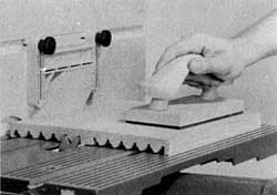
One facet of woodworking that nearly always requires working with the molder head accessory is making decorative cuts on stock surfaces (Figure 5-14). The operation doesn’t differ from usual procedures; it’s the spacing of the cuts that is critical. Good work results when you are careful when making and changing settings.
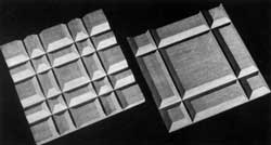
Surface-molded pieces can be used as is, as decorative inset panels in furniture projects, or they can be the base material for fancy moldings. Once the surface molding is finished, the work can be strip-cut into wide or narrow pieces (Figure 5-15).
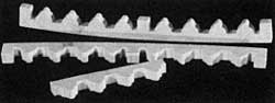
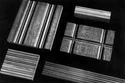
Other examples of surface-molded pieces are shown in Figures 5-16 and 5-17. Those in the latter photo were done with a set of 90° Vee-knives.
Remember, when you make cuts that cross each other, make the cross-grain cuts first, and make them very slowly. Even so, they will not be as smooth as those made with the grain. A light sanding of the cross-grain cut surfaces will improve them.
Forming Joints
When the molder head is equipped with 1″ jointer knives, you can use it for joinery. For example, you can cut a rabbet (Figure 5-18) by holding the work flat on the table and moving it slowly and steadily throughout the pass. To form a tongue, just cut back-to-back rabbets (Figure 5-19). Other molder knife profiles are used to produce joints; among them are the glue joint cutter and the tongue-and-groove set.