In the table saw mode, the Mark V can perform a variety of operations. Kerfing, or thinning out, allows you to bend wood without steaming. Kerfing can also be used for a decorative effect. You can also cut coves, inlays, and raised or pierced panels. Warning: Many of the special operations require the removal of the upper saw guard. Whenever the upper saw guard is removed, keep the lower saw guard in place and work with extreme caution.
Bending Wood
Whether in a home workshop or a commercial establishment, most woodworkers often find it necessary to bend wood to a particular shape. It may be needed on a furniture project-the apron on a drum table or round stool-or on other projects like a garden arbor with an arched top or a doorway with a semi-circular upper structure. Commercial establishments, of course, can bend wood to almost any shape by steaming it or using chemicals to make it flexible. In the home workshop, you don’t usually have the special bending equipment, but you can still do an impressive amount of wood bending just by working on the table saw and using either the kerfing technique or a thinning out process. You must use straight grain lumber for any bending.
Kerfing
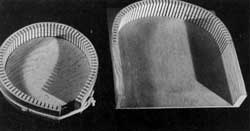
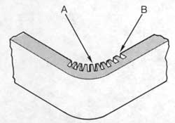
The most popular method of bending wood without steaming is by kerfing (Figure 4-1). What this method accomplishes is a reduction in stock thickness, while allowing room (between the cuts) so the wood can bend back on itself. The depth of the kerfs and their spacing are the important factors and are variable. Deep kerfs, closely spaced, allow the sharpest bends (Figure 4-2).
To bend wood with minimum loss of strength, proper kerf depth and spacing should be determined using a simple test.
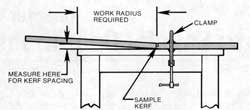
Make a sample kert in a test piece of stock that you wish to bend (Figure 4-3). In 3/4″ stock try a kerf that is 5/8″ to 11/16″ deep. Position the test piece, kerf side up, on a flat surface and hold it in place with a clamp on the right side of the kerf. The distance from the kerf to the edge of the surface on which you have placed the work should equal the radius of the bend you need. Lift the stock at its free end until the kerf closes and then measure the amount of lift at the edge of the table. This tells you the distance required between kerfs.
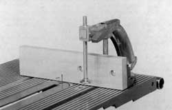
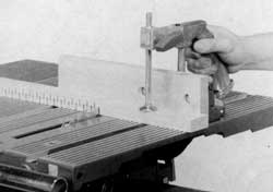
Since work like this calls for a considerable number of kerfs correctly spaced, you should work with a kerf spacing guide like the one shown in Figure 4-4. After you have secured the guide to the miter gauge, cut a saw slot through it and then drill a hole for a nail to serve as the guide pin, spacing it away from the slot a distance equal to the required kerf spacing. Make the first kerf with the workpiece butted against the guide pin. The distance between the remaining cuts is automatically gauged by placing the last kert over the guide pin (Figure 4-5). When the kerfs must be cut in a central area of the stock, make the first cut without using the guide.

To calculate the number of cuts, first find the circumference of the circle that will form the corner of the project. Divide this number by the total number of corners on the project. This will be the length of one corner. Divide the length of the corner by the total width of the saw kert plus the spacing between the kerfs. This will give you the number of cuts you’ll need to make. The formula for this is:
Circumference * Number of Corners = Corner Length
Corner Length * (Kerf Width + Kerf Spacing) = Number of Cuts
Example: Calculating the number of cuts for a 12″ dia. circle, used on a four corner project, with a saw kert of 1/8″, and kerf spacing of 3/4″.
Circumference = 3.14 x 12″ = 37.68″
37.68″ / 4 = 9.42″
9.42″ (1/8″ + 3/4″) = 9.42″ 7/8″(.875) = 10.77 or 11 cuts
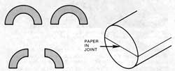
When kerfing is complete, bend the wood slowly until the curve you need is achieved. Wetting the wood with hot water (even if you must soak it awhile) will help the bending process. Also, use a tie strip, tack-nailed in place, to hold the part’s shape until it is permanently attached on an assembly.
You can form irregular curves if you do the kerfing on both sides of the stock and/or vary the kerf spacing. When the kerfing is exposed, veneers may be glued in place to conceal the cuts. If you’re working on an outdoor project, coat the kerts with waterproof glue before making the bend. Wood dough or putty can be used to fill the crevices. When the work has been correctly sanded and finished, it will require a close examination to reveal the method used to make the bend.
Thinning Out
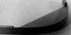
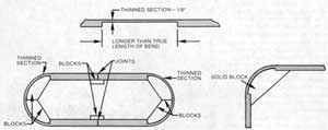
When thinning out, the stock’s thickness is reduced the full length of the bend area (Figure 4-6). In effect, you are producing a length of veneer which is an integral part of the wood. The thinning out can be done with the dado or molder head. It can also be done by resawing the stock on the bandsaw. This method permits very sharp bends; but, since the veneer area won’t have much rigidity or strength, corner blocks should be used to provide structural strength (Figure 4-7). Thinned out sections that have the wood grain running lengthwise will be stronger than those where the grain runs crosswise.
Coving
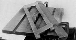
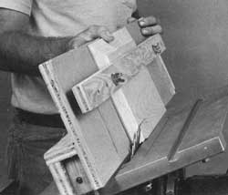
Coving is a unique table saw operation in that the work is fed obliquely across the blade (Figure 4-8) It is a lengthy process because the shape is achieved by making numerous passes with the saw blade’s projection increased by no more than 1/16″ each pass. Coving can be done with the table set at 90° to cut a circular cove or with the table tilted to cut an elliptical cove. If a narrow edge cove is needed, either cut it on a wide piece of stock and cut away the scrap when coving is complete or cut the edge cove from a center cove. Warning: The cutting action is essentially a scraping one, so trying to rush by using more than 1/16″ blade projection is not safe. The blade will tend to cut rather than scrape and the action will cause the workpiece to move away from the guide strip and kick back. The first thing to do is
make the parallel rule fixture that is diagram-med in Figure 4-9. The angle of the cut determines the width of the cove. Set the distance between the fixture’s long legs to equal the width of the arch you want (Figure 4-10). Next, set the saw blade’s projection to equal the depth of the cove and then place the fixture so its long inside edges just touch at the front and rear of the blade. With the parallel rule so positioned, clamp a guide strip to the worktable at the angle determined by the rule (Figure 4-11). The guide strip must be positioned on the infeed side of the blade only so the cutting action forces the stock into the guide strip. The distance between the guide strip and the saw blade will determine whether the cut will be centered, off center, or on an edge of the stock.

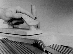
Start the work by setting the blade’s projection to no more than 1/16″. Use a push block to hold the workpiece firmly against the guide strip and make the pass very slowly. Pay special attention to how you place and use your hands. Warning: Coving is done without the upper saw guard In place so work with extreme caution. Use a feather board and push block to support and guide the workpiece. Never cut edge coves that will be wider than half the stock width. Avoid placing your hands over the blade or in line with the cut. After the first pass, increase the blade’s projection another 1/16″ and make a second pass. Continue in this manner until you have arrived at the arch’s depth.
This kind of cut can be made on stock edges (Figure 4-12), but be sure of hand position and that the cove is no wider than half the stock width. With all coving operations, you can clamp a second guide strip to the table parallel to the first one. The distance between the strips equals the width of the stock. Thus you have a “road” along which you move the stock. If you wish to speed up the operation, you can do so by cutting kerfs to remove the bulk of the waste material (Figure 4-13).
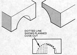
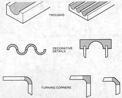
Coving is a useful technique because it can be used to produce components like those shown in Figure 4-14. Shapes like those in Figure 4-15 are possible if the coving is done on pieces that have first been lathe turned. The coves that are formed are not true semi-circles; this could only occur if the work were fed across the blade at right angles to it. However, some work with a drum sander or hand sanding is usually sufficient to true up the arch.
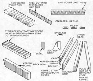
Kerf Moldings
One way to individualize your work is with original molding designs like those in Figure 4-16. Most of these are done by using the kerfing method described for wood bending or variations of it. Thus, the kerf spacing guide used for bending kerfs can also be used for moldings. Instead of making the kerts on only one face of the stock, the work is turned over for each new cut (Figure 4-17). A fixture that is used for finger joints may also be used should you wish to produce wide notches using the dado head. Another way to produce exclusive moldings is to strip-cut pieces from stock that has been surface contoured with the molder.
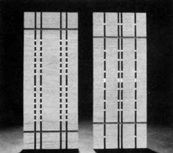
Piercing
Piercing is done on the table saw by running intersecting cuts on opposite surfaces of the stock. When the projection of the saw blade is a bit more than half the stock’s thickness, openings in the work result where the cuts cross (Figure 4-18). The overall pattern is affected by the kerfs as well as the openings, so it is important to visualize the results before doing the cutting. It’s wise to go through the procedure on scrap material. By using a simple guide like the one shown in use in Figure 4-19, the kerfing can be done at an angle, which adds another dimension to the technique. Piercing can be done with a regular saw blade or with a dado head for wider cuts. Warning: Piercing is done without the upper saw guard in place so work with extreme caution.
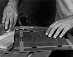
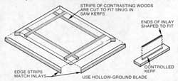
Forming Simple Inlays
The idea in forming simple inlays is to cut kerfs (Figure 4-20), with a saw blade or dado head, and then fill the grooves with a contrasting wood (Figure 4-21) that is cut to fit. Working in this manner, you’ll have a tight, professional looking fit when the inlaid strips cross each other. Warning: Inlays are formed without the upper saw guard in place so work with extreme caution.
Cut all the kerfs that run in one direction and inlay the strips. Then cut the crossing kerfs. The second set of inlay strips will form perfect joints where they cross the first ones. Always cut the inlay strips so they are a bit thicker than necessary. You can sand them, after installation, so they will be flush with adjacent surfaces.
Raised Panels
Making raised panels for room doors, cabinet doors, or wall pan-eling will be easy with a fixture that you can use with your table saw.
The fixture straddles the rip fence and will hold your stock securely as you cut the bevels for your panel.
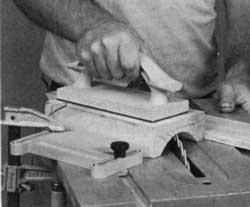
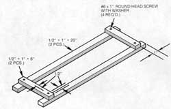
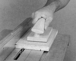
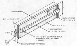
Make the fixture (Figure 4-22) by first cutting all parts to size. Drill the adjustable clamp holes where shown 2″ apart. Use glue and screws to assemble all parts except the clamping strip. Glue fine-grit sandpaper onto the face of the fixture. Note: This fixture can double as a tenoning fixture. Insert the workpiece against the back-up strip and cut a tenon on the end of the workpiece.
To use the fixture, tilt the table 5° to 15°–the greater the tilt, the narrower the bevel. Use a carbide-tipped blade for a smoother cut. Place your stock in the fixture, put the clamping bolts as close to the panel as possible, and tighten the wing nuts. The sandpaper will also help keep the panel in place. Position the rip fence on the right side of the blade. Set table height so the inside edge of the blade penetrates through the stock (Figure 4-23). Turn off the machine after each pass and reset the panel in the fixture to cut each side of the panel.